Table of Contents
Advertisement
Quick Links
Safety warning
THIS KIT IS NOT FOR BEGINNERS !
This kit uses high and potentially lethal voltages. Under no circumstance should someone undertake the realisation of
this kit unless he has full knowledge about safely handling main powered devices.
Follow the testing procedure in the shown order. If one test fails, find out the problem, correct it then resume.
Always unplug power between steps and discharge high voltage capacitors as described below.
Always use an insulated screw driver to adjust the trimmers. There are several points that carry high voltage that may kill
you if you accidentally touch them.
It is very easy to create shortcuts when moving the DMM probes. Be very careful because most of the time, shortcuts
are fatal to the circuits.
Step
1.
Jumpers setting
2.
Short circuit check
3.
Test setup
4
Discharge cable
IMPORTANT
Copyright ©2008 SoundSkulptor
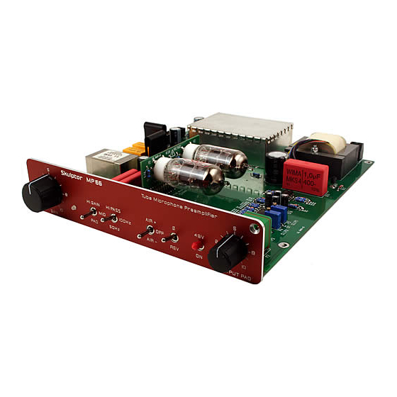
MP66 Setup guide
Description
Install 2 jumpers on JMP1 to set the transformer ratio to 1:5.
Do a basic short circuit check with your digital multimeter (DMM) set to Ohms :
Between Test point TP2 (GND) and TP7 (V+300).
You should get several hundred of kilo-Ohms. If it is not the case, find out and fix the
short before applying power.
At this point, you need an assembled and wired SKMP case.
Install your MP66 in 2 free slots. Do not forget to place the mylar insulator sheet
underneath the PCB. Connect a ribbon cable between the DI02 and the MP66 board
(look at the "SKMP assembly guide"). Disconnect all other mic pre's by removing the
ribbon cables.
Connect the power supply leaving the mains plug disconnected.
Make sure NO tube is installed on your MP66 board .
Prepare a discharge cable for the high voltage capacitors.
The circuit uses 300V DC voltages. Several
electrolytic capacitors are charged to this
potential. When power is removed, the tube
heaters turn off, leaving the tubes in a high
impedance state preventing the capacitors
discharge. This means that very high potentials
will remain on the circuit many minutes after the
power has been removed.
Before putting your fingers on the circuit, it is
necessary to discharge the capacitors.
Use a piece of insulated wire and a 1K to 10K
resistor connected to ground. The ground can
be taken on the ground bar that links the XLR plugs.
To discharge the caps, touch TP7 a few seconds with the resistor leg.
Document revision 1.1 – Last modification : 27/06/11
www.soundskulptor.com
Advertisement
Table of Contents

Related Manuals for Sound Skulptor MP66


Summary of Contents for Sound Skulptor MP66
- Page 1 At this point, you need an assembled and wired SKMP case. Install your MP66 in 2 free slots. Do not forget to place the mylar insulator sheet underneath the PCB. Connect a ribbon cable between the DI02 and the MP66 board (look at the “SKMP assembly guide”).
- Page 2 www.soundskulptor.com Document revision 1.1 – Last modification : 27/06/11 Step Description High voltage check Set your DMM to DC Volts on a 500 V scale and connect it between TP2 (GND) and TP7 (V+). Use test hooks and be careful not to create shortcuts. Plug in power and check that the 3 LEDs on the power supply unit are lighting normally.
- Page 3 www.soundskulptor.com Document revision 1.1 – Last modification : 27/06/11 Step Description Clip LED setup Warning : Do not forget to set your 48V phantom switch to OFF. This setup will be based on voltage levels rather than on actual clipping because, in tube preamps, the clipping comes in very progressively and it is difficult to hear.
Need help?
Do you have a question about the MP66 and is the answer not in the manual?
Questions and answers