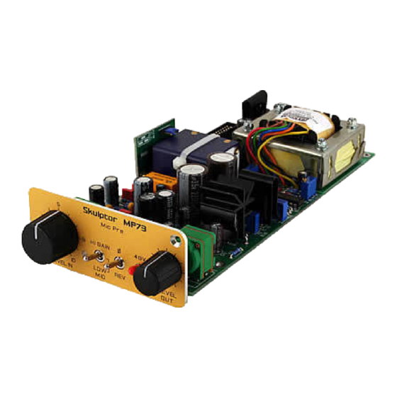
Table of Contents
Advertisement
Quick Links
MP73 Assembly guide
MP73 Assembly guide
MP73 Assembly guide
MP73 Assembly guide
Safety warning
Safety warning
Safety warning
Safety warning
The kits are main powered and use potentially lethal voltages. Under no circumstance should someone undertake the
realisation of a kit unless he has full knowledge about safely handling main powered devices.
Please read the "DIY guide" before beginning.
Print or open the following documents :
• MP73 Schematics
• MP73 Components layout
• MP73 Parts list
• SKMP Assembly guide
• MP73 Setup guide
Follow this guide from item number 1 till the end, in this order. The assembly order is based on components height, from
low to high profile, in order to ease the soldering process : The component you are soldering is always taller than the
previously assembled ones and it is pressing nicely against the work area foam.
Copyright ©2007 SoundSkulptor
Document revision 1.3 – Last modification : 21/02/09
www.soundskulptor.com
Advertisement
Table of Contents

Summary of Contents for Sound Skulptor MP73
- Page 1 Please read the “DIY guide” before beginning. Print or open the following documents : • MP73 Schematics • MP73 Components layout • MP73 Parts list • SKMP Assembly guide • MP73 Setup guide Follow this guide from item number 1 till the end, in this order.
- Page 2 www.soundskulptor.com Document revision 1.3 – Last modification : 21/02/09 Copyright ©2007 SoundSkulptor...
- Page 3 www.soundskulptor.com Document revision 1.3 – Last modification : 21/02/09 Copyright ©2007 SoundSkulptor...
- Page 4 Shorten the leads to the necessary length, around 6 cm. Strip on 5mm and tin. Insert in the pad hole and bend the tinned tip flat on the pad before soldering. Cut flush. The wire colour/pad number correspondence is indicated in the “MP73 Components layout” document. Copyright ©2007 SoundSkulptor...
- Page 5 Make a full visual check. Any missing component on the board ? Any remaining component in the box ? When everything is correct, install the input and output XLR's as described in the SKMP Assembly Guide. Your MP73 is now ready for test and setup. Please follow instructions in the “MP73 Setup” document. Copyright ©2007 SoundSkulptor...
- Page 6 www.soundskulptor.com Document revision 1.1 – Last modification : 07/01/15 V12V2 adapter board Assembly guide V12V2 adapter board Assembly guide V12V2 adapter board Assembly guide V12V2 adapter board Assembly guide Safety warning Safety warning Safety warning Safety warning The kits are main powered and use potentially lethal voltages. Under no circumstance should someone undertake the realisation of a kit unless he has full knowledge about safely handling main powered devices.
- Page 7 Wires Wires Wires For MP12, MP32, MP73 cut two blue/red pairs of 8cm wires. For MP66 cut one 8cm pair and one 17cm pair of blue/red wires. Strip 5mm of one end of each wire. Solder the red wires at the bottom side of the PCB on the IN+ and OUT+ pads. Long wire on output for the MP66.
- Page 8 www.soundskulptor.com Document revision 1.1 – Last modification : 07/01/15 V12V2 Adapter board - Assembly guide V12V2 Adapter board - Assembly guide V12V2 Adapter board - Assembly guide V12V2 Adapter board - Assembly guide Copyright ©2011-today SoundSkulptor...


Need help?
Do you have a question about the MP73 and is the answer not in the manual?
Questions and answers