Table of Contents
Advertisement
Quick Links
Advertisement
Table of Contents

Related Manuals for Supermicro SuperServer ARS-111GL-NHR


Summary of Contents for Supermicro SuperServer ARS-111GL-NHR
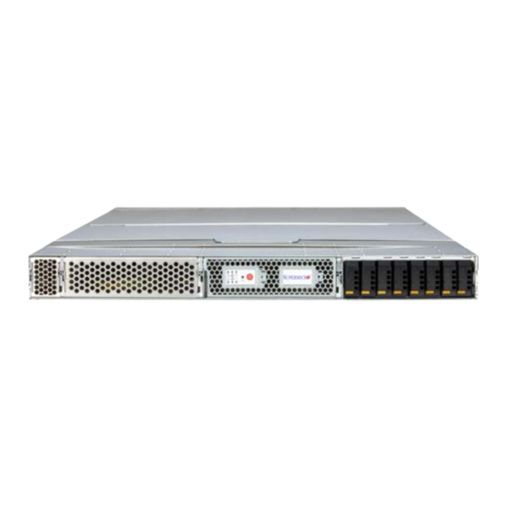
- Page 1 SuperServer ® ARS-111GL-NHR USER’S MANUAL Revision 1.0...
- Page 2 State of California, USA. The State of California, County of Santa Clara shall be the exclusive venue for the resolution drivers/utilities and the user’s manual for your server. of any such disputes. Supermicro's total liability for all claims will not exceed the price paid for the hardware product. •...
-
Page 3: Table Of Contents
Preface Preface Contents Removing the Outer Rails from the Rack .................29 Chapter 3 Maintenance and Component Installation Contacting Supermicro ......................7 3.1 Removing Power .......................30 Chapter 1 Introduction 3.2 Accessing the System ......................31 1.1 Overview ..........................8 Removing the Top Cover ....................31 1.2 System Features ........................9... - Page 4 Returning Merchandise for Service ...................72 Tel: +1 (408) 503-8000 7.7 Feedback ..........................72 Fax: +1 (408) 503-8008 7.8 Contacting Supermicro .......................73 Email: marketing@supermicro.com (General Information) Appendix A Standardized Warning Statements for AC Systems Sales-USA@supermicro.com (Sales Inquiries) Appendix B System Specifications Government_Sales-USA@supermicro.com (Gov. Sales Inquiries) support@supermicro.com (Technical Support)
- Page 5 1U: 17.33" x 1.75" x 37" (440 x 44 x 940 mm (W x H x D) Notes: A Quick Reference Guide can be found on the product page of the Supermicro website. The following safety models associated with the ARS-111GL-NHR have been certified as...
- Page 6 Alerts operator to several states (noted in the table below). Indicates that the power supply is plugged in, and is in an abnormal state. Solid Amber The system might need service. Please contact Supermicro technical support. No AC power to modules...
- Page 7 Chapter 1: Introduction Chapter 1: Introduction Rear View Information LED Color, Status Description Red, solid An overheating condition has occurred Red, blinking at 1 Hz Fan failure, check for an inoperative fan Red, blinking at 0.25 Hz Power failure, check for a non-operational power supply Red, blinking at 10 Hz CPLD recovery mode error Blue, solid...
- Page 8 Chapter 1: Introduction Chapter 1: Introduction Top View Grace CPU Superchip The ARS-111GL-NHR features one Grace CPU Superchip with attached LPDDR5x memory on a mezzanine module, and a 900 GB/s NVLink, chip-to-chip on the module. There is no Rear off-the-module NVLink support Grace CPU Superchip Overview Core Count 72 Arm Neoverse V2 Cores with 4 x128b SVE2...
- Page 9 Chapter 1: Introduction Chapter 1: Introduction 1.3 Motherboard Layout Quick Reference Table Below is a layout of the G1SMH-G motherboard. See the table on the following page for descriptions. Description Status HB_LED1 CPLD Initialization Green Blinking: CPLD initialized Before pressing PWRBTN1: Yellow Solid LED1 EROT Detected JPWR1...
- Page 10 Chapter 1: Introduction Chapter 1: Introduction Motherboard Block Diagram Connector Description JNCSIBF3 NVIDIA BlueField-3 DPU Card NCSI Sideband Connector JSB1 74-Pin IO Sideband Signals Connector JSB2 20-Pin Main Sideband Signals Connector JSB3 Front Control Board Debug Header JPFR1 PFR Debug JPFR2 PFR Operation JPFR3...
- Page 11 Chapter 2: Server Installation Chapter 2: Server Installation Chapter 2 • In single rack installations, stabilizers should be attached to the rack. In multiple rack in- stallations, the racks should be coupled together. • Always make sure the rack is stable before extending a server or other component fromthe Chassis Installation rack.
- Page 12 Chapter 2: Server Installation Chapter 2: Server Installation 2.3 Installing the System into a Rack Circuit Overloading Consideration should be given to the connection of the equipment to the power supply circuitry This section provides information on installing the SCGP101/102 chassis into a rack unit and the effect that any possible overloading of circuits might have on overcurrent protection with the quick-release rails provided.
- Page 13 Chapter 2: Server Installation Chapter 2: Server Installation Releasing the Inner Rail Installing the Inner Rails on the Chassis It is necessary to release the inner rail from the middle and outer rails before installing the Installing the Inner Rails inner rail on the chassis.
- Page 14 Chapter 2: Server Installation Chapter 2: Server Installation Installing the Outer Rails on the Rack Installing into the Rack Installing the Outer Rails After the rails are installed on the chassis and on the rack, the server can be installed in the rack.
-
Page 15: Removing The Outer Rails From The Rack
Chapter 2: Server Installation Chapter 2: Server Installation Removing the Chassis from the Rack Removing the Outer Rails from the Rack Caution: The chassis is heavy and requires two to three people to lift it out. In the uncommon event that it is necessary to remove the outer rails from the rack, follow these instructions. -
Page 16: Chapter 3 Maintenance And Component Installation
Chapter 3: Maintenance and Component Installation Chapter 3: Maintenance and Component Installation Chapter 3 3.2 Accessing the System Note: The chassis features a removable top cover for access to the internal components. When performing service on components inside the system, remove the system from the rack Maintenance and Component Installation and place it on a work bench or desk. -
Page 17: Processor And Heatsink Installation
• Refer to the Supermicro website for updates on the NVIDIA GH200 Grace Hopper Super- chip module support. Installing the Superchip onto the Motherboard 1. Remove the plastic protector on the CPU and GPU connector. - Page 18 Chapter 3: Maintenance and Component Installation Chapter 3: Maintenance and Component Installation Superchip Top View 5. Place thermal pads on the module. The thermal pads are shown as red rectangles above. 8. Using a torque of 5.2 lb-in (0.587 N-m), secure each heatsink onto the NVIDIA GH200 Grace Hopper Superchip module with four screws.
-
Page 19: Memory Support
Chapter 3: Maintenance and Component Installation Chapter 3: Maintenance and Component Installation 3.4 Memory Support 3.5 Motherboard Battery The motherboard uses non-volatile memory to retain system information when system power Memory Support is removed. This memory is powered by a lithium battery residing on the motherboard. The G1SMH-G supports up to 480 GB of ECC LPDDR5 and 96 GB of HBM. -
Page 20: Chassis Components
The CSE-MG102TS chassis supports up to two E1.S NVMe SSD drives using mounting trays this module needs to be serviced, it is seldom removed and is shown here for information or carriers. Note: Enterprise-level storage drives are recommended for use in Supermicro purposes. -
Page 21: Power Supply
New units can be ordered directly from Supermicro or authorized distributors. Replacing a System Fan These power supplies are auto-switching capable. This feature enables them to automatically 1. -
Page 22: Chapter 4 Motherboard Connections
Chapter 4: Motherboard Connections Chapter 4: Motherboard Connections Chapter 4 4.2 Headers and Connectors Motherboard Connections 12 V 8-pin IO Board Power Supply Connector (JPWR6) JPWR6 is an 8-pin MICRO POWER PLUS power input to provide power to the I/O board. Refer to the table below for pin definitions. - Page 23 Port 80 connection. Use this header to enhance system performance and data security. 74-pin IO Sideband Power Connector Refer to the table below for pin definitions. Please go to the following link for more information Pin Definitions on the TPM: http://www.supermicro.com/manuals/other/TPM.pdf. Pin# Definition Pin# Definition...
-
Page 24: I/O Ports
Chapter 4: Motherboard Connections Chapter 4: Motherboard Connections 4.3 I/O Ports Power SMB Header (PWRI2C) Power System Management Bus (I C) header monitors power supply, fan and system I/O ports are located in a module that installs into a rear expansion slot. temperatures. -
Page 25: Led Indicators
Chapter 4: Motherboard Connections Chapter 4: Motherboard Connections 4.4 LED Indicators M.2 Activity LEDs ACT_LED1 and ACT_LED2 are onboard M.2 LEDs. When these LEDs are blinking green, UID LED (UID_LED1) the M.2 SSD is active. The UID LED is located next to two buttons at one of the corners of the motherboard. One M.2 Activity LEDs of the buttons is the UIDBTN1 button. -
Page 26: Chapter 5 Software
Chapter 5: Software Chapter 5: Software Chapter 5 2. Download the ISO image to a location that can be accessed by the browser. 3. Set up the ISO image as virtual media. Software a. From the left hand menu, expand Operations. b. - Page 27 Chapter 5: Software Chapter 5: Software c. In the boot menu, select UEFI OpenBMC Virtual Media Device as the boot device and press Enter. d. Follow the instructions in Installing Ubuntu Server.
- Page 28 Chapter 5: Software Chapter 5: Software Installing Ubuntu Server name>:dhcp::: instead of ip=dhcp, and this format can also be used to configure the interface with a static IP address configuration. Refer to the nfsroot documentation for more information Prerequisites: This section assumes you have already booted the Ubuntu ISO image. about how to use this kernel boot parameter.
- Page 29 Chapter 5: Software Chapter 5: Software 4. Follow the installer prompts to configure the manual installation. 6. Select the Keyboard configuration. 5. Select the text-based installer mode and update the installer if necessary.
- Page 30 Chapter 5: Software Chapter 5: Software 7. Select the base for the installation.
- Page 31 Chapter 5: Software Chapter 5: Software 8. Configure the network connections, proxy settings, and Ubuntu archive mirror. 10. Select the system hostname and create a username and password. 11. Select or decline Ubuntu Pro option for extended support from Canonical. 9.
- Page 32 Chapter 5: Software Chapter 5: Software 12. Select the system SSH server and settings. 13. Select the featured Ubuntu server snaps. 14. System installation begins, wait for the Install Complete banner and the Reboot Now option before proceeding to the next step. 15.
-
Page 33: Superdoctor® 5
Note: Platform-dependent workarounds in the form of kernel boot parameters can be specified with GRUB_CMDLINE_LINUX_DEFAULT in this file. The Supermicro SuperDoctor 5 is a program that functions in a command-line or web-based 18. From the shell, to update grub and install the NVIDIA optimized Ubuntu kernel variant, interface for Windows and Linux operating systems. -
Page 34: Chapter 7 Troubleshooting And Support
Supermicro Phone and Addresses 7.1 Information Resources Website A great deal of information is available on the Supermicro website. 7.2 Baseboard Management Controller (BMC) The system supports the Baseboard Management Controller (BMC). BMC is used to provide remote access, monitoring, and management. There are several BIOS settings that are related to BMC. -
Page 35: Before Power On
4. Install the CPU (making sure it is fully seated) and connect the front panel connectors to 2. Memory: Make sure that the memory modules are supported. Refer to the product page on our website at www.supermicro.com. Test the modules using memtest86 or a similar utility. the motherboard. - Page 36 6. To find out if a component is good, swap this component with a new one to see if the a motherboard manufacturer, Supermicro also sells motherboards through its channels, so it system will work properly. If so, then the old component is bad. You can also install the is best to first check with your distributor or reseller for troubleshooting services.
- Page 37 Fax: +31 (0) 73-6416525 Email: Sales_Europe@supermicro.com (Sales Inquiries) Supermicro values your feedback as we strive to improve our customer experience in all facets of our business. To provide feedback on our manuals, please email us at techwriterteam@ Support_Europe@supermicro.com (Technical Support) supermicro.com.
- Page 38 Este símbolo de aviso indica peligro. Existe riesgo para su integridad física. Antes de Read this appendix in its entirety before installing or configuring components in the Supermicro manipular cualquier equipo, considere los riesgos de la corriente eléctrica y familiarícese chassis.
- Page 39 Appendix A: Warning Statements Appendix A: Warning Statements . ٌ ا ك ً ف حالة و ٌ يك أى تتسبب ف اصابة جسذ ة ٌ هذا الزهز ع ٌ خطز !تحذ ز Warnung قبل أى تعول عىل أي هعذات،يك عىل علن بالوخاطز ال ا ٌجوة عي الذوائز Vor dem Anschließen des Systems an die Stromquelle die Installationsanweisungen lesen.
- Page 40 Appendix A: Warning Statements Appendix A: Warning Statements Power Disconnection Warning Warnung Dieses Produkt ist darauf angewiesen, dass im Gebäude ein Kurzschluss- bzw. Warning! The system must be disconnected from all sources of power and the power Überstromschutz installiert ist. Stellen Sie sicher, dass der Nennwert der Schutzvorrichtung cord removed from the power supply module(s) before accessing the chassis interior nicht mehr als: 250 V, 20 A beträgt.
- Page 41 Appendix A: Warning Statements Appendix A: Warning Statements אזהרה מפני ניתוק חשמלי !אזהרה Attention יש לנתק את המערכת מכל מקורות החשמל ויש להסיר את כבל החשמלי מהספק Seul le personnel autorisé et le personnel de maintenance qualifié doivent être autorisés à installer, remplacer ou entretenir cet équipement..
- Page 42 Appendix A: Warning Statements Appendix A: Warning Statements Warnung Battery Handling Diese Einheit ist zur Installation in Bereichen mit beschränktem Zutritt vorgesehen. Der Zutritt zu derartigen Bereichen ist nur mit einem Spezialwerkzeug, Schloss und Schlüssel oder einer CAUTION: There is risk of explosion if the battery is replaced by an incorrect type. sonstigen Sicherheitsvorkehrung möglich.
- Page 43 Appendix A: Warning Statements Appendix A: Warning Statements .هناك خطر االنفجار إذا تم استبدال البطارية بنوع غري صحيح ¡Advertencia! اسحبذال البطارية Puede que esta unidad tenga más de una conexión para fuentes de alimentación. Para cortar por completo el suministro de energía, deben desconectarse todas las conexiones. فقط...
- Page 44 Appendix A: Warning Statements Appendix A: Warning Statements Backplane Voltage هناك خطز مه التيار الكهزبايئ أوالطاقة املىجىدة عىل اللىحة عندما يكىن النظام يعمل كه حذ ر ا عند خدمة هذا الجهاس Warning! Hazardous voltage or energy is present on the backplane when the system is operating.
- Page 45 Appendix A: Warning Statements Appendix A: Warning Statements תיאום חוקי החשמל הארצי Attention !אזהרה La mise au rebut ou le recyclage de ce produit sont généralement soumis à des lois et/ou .התקנת הציוד חייבת להיות תואמת לחוקי החשמל המקומיים והארציים directives de respect de l'environnement.
- Page 46 제거할 때 팬은 여전히 회전하고 있을 수 있습니다. 팬 조림품 외관의 열려있는 부분들로부터 Feuer verursachen. Die Richtlinien untersagen das Nutzen von UL oder CAS zertifizierten 손가락 및 스크류드라이버, 다른 물체들이 가까이 하지 않도록 배치해 주십시오. Kabeln (mit UL/CSA gekennzeichnet), an Geräten oder Produkten die nicht mit Supermicro Waarschuwing gekennzeichnet sind.
- Page 47 .قيرح وأ لطع يف ببستي دق ىرخأ تالوحمو تالباك يأ مادختسا .ميلسلا سباقلاو لصوملا مجح لبق نم ةدمتعملا تالباكلا مادختسا تادعملاو ةيئابرهكلا ةزهجألل ةمالسلا نوناق رظحيUL وأCSA ( ةمالع لمحت يتلاوUL/CSA) لبق نم ةددحملاو ةينعملا تاجتنملا ريغ ىرخأ تادعم يأ عمSupermicro.
- Page 48 Appendix B: System Specifications Appendix B: System Specifications Appendix B Operating Environment Operating Temperature: 10ºC to 35ºC (50ºF to 95ºF) Non-operating Temperature: -40ºC to 60ºC (-40ºF to 140ºF) Operating Relative Humidity: 8% to 90% (non-condensing) System Specifications Non-operating Relative Humidity: 5% to 95% (non-condensing) Regulatory Compliance FCC, ICES, CE, UKCA, VCCI, RCM, NRTL, CB Applied Directives, Standards...
- Page 49 Appendix B: System Specifications General Data Center Environmental Specifications NEEDED? Particulate contamination specifications Air filtration: Data centers must be kept clean to Class 8 of ISO 14644-1 (ISO 2015). The air entering the data center should be filtered with a MERV 11 filter or better. The air within the data center should be continuously filtered with a MERV 8 filter or better.
Need help?
Do you have a question about the SuperServer ARS-111GL-NHR and is the answer not in the manual?
Questions and answers