Table of Contents
Advertisement
Quick Links
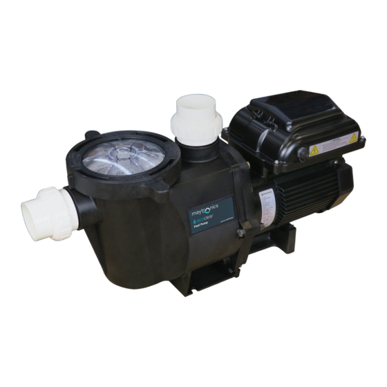
1500-VS Pool Pump
Installation
& Operation
Manual
Should the installer or owner be unfamiliar with the correct installation or operation
of this type of equipment you should contact the distributor/manufacturer for the
correct advice before proceeding with the installation or operation of this product.
The pump operator or owner must be provided with this owner's manual.
Manufactured by
Advertisement
Table of Contents

Related Manuals for Pentair maytronics ecoclea 1500-VS


Summary of Contents for Pentair maytronics ecoclea 1500-VS
- Page 1 1500-VS Pool Pump Installation & Operation Manual Should the installer or owner be unfamiliar with the correct installation or operation of this type of equipment you should contact the distributor/manufacturer for the correct advice before proceeding with the installation or operation of this product. The pump operator or owner must be provided with this owner’s manual.
- Page 2 1500-VS Pool Pump Owner’s Manual...
-
Page 3: Table Of Contents
CONTENTS Page Features and Benefits Technical Information Model Data Hydraulic Performance Dimensions Installation Pump Positioning Piping Pool Outlets Electrical Equipotential Bonding Operation Priming the Pump Control Panel Overview Setting Clock Using Default Schedule Custom Schedules Operation While Pump is Running Quick Clean Keypad Lockout Factory Reset... -
Page 4: Features And Benefits
FEATURES & BENEFITS The Ecoclear® 1500-VS Pool Pump is the ideal pump for new or existing pools. Utilising advanced hydraulic design and the latest technology in permanent magnet, variable speed motors, the Ecoclear® 1500-VS Pool Pump has the perfect combination of efficiency and performance. -
Page 5: Technical Information
TECHNICAL INFORMATION Model Data RPM: Low 1400RPM Med 2200RPM High 3000RPM Override: 3150RPM Electrical Rating: 230-240V 50Hz single phase Rated Current: Low: 1.0A (max) Med: 3.2A (max) High: 7.4A (max) Override: 8.6A Motor Output Power (P Low: 175W (max) Med: 560W (max) High: 1360W (max) Override: 1575W Motor Input Power (P... -
Page 6: Hydraulic Performance
TECHNICAL INFORMATION Hydraulic Performance WhisperFlo VS 1500 Ecoclear® 1500-VS Pool Pump 3150 RPM 2800 RPM 2400 RPM 2000 RPM 1600 RPM 1200 RPM Flow (LPM) Ecoclear® 1500-VS Pool Pump Performance Chart Dimensions 1500-VS Pool Pump Owner’s Manual... -
Page 7: Installation
INSTALLATION The pump must be installed and serviced by a suitably qualified person in order to avoid hazard. Incorrectly installed or tested equipment may fail, causing severe injury or property damage. These instructions are a guide only. Should you the installer or owner of the product be unfamiliar with the correct installation or operation of this product you should contact a suitably qualified person for advice. -
Page 8: Piping
INSTALLATION 2. Piping For best performance, allow pump suction inlet height to be as far below water level as possible and allow the use of short, direct suction pipe with minimum bends (to reduce friction losses). a. Use only Australian Standard PVC pressure pipe. For best performance use at least 50mm diameter pipe for all connections to the pump. -
Page 9: Electrical
INSTALLATION 4. Electrical Do not use extension leads as they are unsafe in and around the Pool Zone. Hazardous voltage. Can shock, burn or cause death. To avoid dangerous or fatal electrical shock, turn OFF power to pump and remove plug from outlet before working on electrical connections. a. -
Page 10: Operation
OPERATION NEVER run pump dry. Running pump dry may damage seals, causing leakage and flooding. Fill pump with water before starting motor. Freezing conditions will damage the unit, as water expands as it freezes. Ensure that the Ecoclear® 1500-VS Pool Pump is located so that it is not prone to freezing, or ensure that the product is disconnected and dried of water during cold conditions. -
Page 11: Control Panel Overview
OPERATION Control Panel Overview (4) Display Mode LED Indicators (5) Display (1) Speed Buttons Button (6) Quick Clean (2) External Button Control Only LED Indicator (7) Power LED Indicator (3) Start/Stop Button (8) “+” and “-” Arrows If power is connected to the Ecoclear® 1500-VS Pool Pump Variable Speed Pump motor, pressing any of the following buttons referred to in this section could result in the motor starting. -
Page 12: Setting Clock
OPERATION Activating/Deactivating the Time Clock When the pump is first plugged in, the clock will not be turned on. This means the pump will start from speed 1, whenever the pump is powered up. The pump will then proceed to speed 2, after the programmed duration for speed 1 has elapsed and so on for speed 3. -
Page 13: Using Default Schedule
OPERATION Using the Default Schedule The default schedule is designed to provide enough daily turnover to service a typical pool. See Table 1 for default schedule. DURATION (Hours) SPEED (RPM) SPEED 1 3000 SPEED 2 1400 SPEED 3 2200 Table 1: Default Schedule SPEED 1 is set to begin at 8:00am and run at 3000 RPM for a duration of 2 hours. -
Page 14: Custom Schedules
OPERATION Custom Schedules To customize the run schedule for your Ecoclear® 1500-VS Pool Pump Variable Speed Pump, the pump must be stopped. Be sure that the Start/Stop button LED is not illuminated. Programming a Custom Schedule: Note: When programming, the LED light next to the parameter (“Speed”, “Time” and “Duration”) you are setting will blink. - Page 15 OPERATION 7. Use the “+” and “-” arrows to adjust the duration for SPEED 1 in hours and minutes. Note: The duration parameter is adjusted in 15 minute increments. 8. Pressing the “1” button will continue to cycle through these parameters, but the changes are immediately saved as they are adjusted.
-
Page 16: Operation While Pump Is Running
OPERATION Operation While Pump is Running If power is connected to the pump motor, pressing any of the following buttons referred to in this section could result in the motor starting. Failure to recognize this could result in personal injury or damage to equipment. Pressing the Display button will cycle through the current parameters. - Page 17 OPERATION Priming This pump is shipped with Priming mode ENABLED. Unless the Priming settings are changed in the menu, be aware that the pump will speed up to the priming speed when the pump is powered on for the first time, and the start/stop button is pressed.
-
Page 18: Quick Clean
OPERATION The installer should set the priming speed to be sufficient for priming the pump from a fresh install, but not so fast that there is a substantial waste of energy during the 5 minute priming window. The time the pump needs to achieve prime can change based on local environmental conditions such as water temperature, atmospheric pressure, and your pool’s water level. -
Page 19: Keypad Lockout
OPERATION 3. Use the “+” and “-” arrows to adjust the speed in RPM for Quick Clean. 2 : 00 4. Press the Quick Clean button again and the display will change to Quick Clean duration. The “Duration” parameter LED will flash while editing. -
Page 20: Factory Reset
OPERATION Factory Reset The drive can be reset to factory settings if necessary. A Factory Reset will wipe out all of the saved user settings that have been programmed, except for the time of day. Be sure that it is necessary before performing a Factory Reset, as the results are immediate. -
Page 21: External Controls
The wire included with the External Control Wiring Kit (Pentair P/N 353129Z) will need to be cut to length for the installation. Do not leave excess wire around the installation, and the wire should be supported by something rigid if conduit is not used. - Page 22 OPERATION POWER RELAY (DPST) R E L A Y R E L A Y 1 R E L A Y 2 R E L A Y 3 R E L A Y 4 RED +5V OUTPUT FOR D.I. TRIGGERS GREEN SPEED 1 DIGITAL INPUT YELLOW SPEED 2 DIGITAL INPUT...
- Page 23 OPERATION EXTERNAL LOW VOLTAGE SUPPLY 5-30 V AC/DC +5V OUTPUT FOR D.I. TRIGGER GROUND GREEN SPEED 1 DIGITAL INPUT YELLOW SPEED 2 DIGITAL INPUT ORANGE SPEED 3 DIGITAL INPUT BROWN SPEED 4 DIGITAL INPUT BLACK GROUND Figure 11: Low Voltage Power Supply Wiring Diagram Note: If the pump has been stopped via the Start/Stop button, the pump will not run until the pump is turned back on by pressing the Start/Stop button.
- Page 24 SERVICE & MAINTENANCE To avoid dangerous or fatal Do not operate pump with trap electrical shock hazard, turn OFF basket missing or damaged. power to pump and remove plug from power outlet before working on pump. • It is essential for the longevity of the pump that regular service and maintenance be carried out.
-
Page 25: Troubleshooting
TROUBLESHOOTING To avoid dangerous or fatal electrical shock hazard, turn OFF power to pump and remove plug from power outlet before working on pump. Troubleshooting Guide SYMPTOM CAUSE REMEDY Low water Suction leaks / lost • Pump must be primed; make sure that pressure, low flow prime. - Page 26 TROUBLESHOOTING SYMPTOM CAUSE REMEDY Pump does not Motor fault. • Refer to motor fault codes. work. No power at outlet. • Use another electrical appliance that is known to work to check power outlet. Blown fuse / • Check and call electrician if necessary. Circuit breaker.
- Page 27 TROUBLESHOOTING Troubleshooting Guide Errors and Alarms If an alarm is triggered the drives LCD screen will display the fault code text and the Ecoclear® 1500-VS Pool Pump Variable Speed Pump will stop running. Disconnect power to the pump and wait until the keypad LEDs have all turned off. At this point, reconnect power to the pump.
-
Page 28: Spare Parts
SPARE PARTS 1500-VS Pool Pump Owner’s Manual... - Page 29 Top cover kit 800047 VS Drive Kit Supply Cord If the supply cord is damaged, it must be replaced by the manufacturer (Pentair), its service agent or similarly qualified person in order to avoid a hazard. 1500-VS Pool Pump Owner’s Manual...
- Page 30 NOTES 1500-VS Pool Pump Owner’s Manual...
- Page 31 NOTES 1500-VS Pool Pump Owner’s Manual...
- Page 32 IMPORTANT Please attach your sales invoice/docket here as proof of purchase should warranty service be required. Please do not return warranty form to Maytronics Australia – Retain for your records. PURCHASED FROM: PURCHASE DATE: SERIAL NO: MODEL NO: Unit 2/91 Rudd Street, Oxley, QLD 4075 | Australia | 1300 693 657 | www.maytronics.com.au Information contained here in remains the property of Maytronics Australia under Australian copyright law.
Need help?
Do you have a question about the maytronics ecoclea 1500-VS and is the answer not in the manual?
Questions and answers
No power to pump. P6 illuminated on Maytronics mineral swim chlorinator. digital screen.