Table of Contents

Related Manuals for Pentair INTELLIFLO 100


Summary of Contents for Pentair INTELLIFLO 100
- Page 1 ® IntelliFlo 4 160 Variable Speed Programmable Pump ™ ™ (Compatible with IntelliTouch , EasyTouch and IntelliComm) Installation and User’s Guide IMPORTANT SAFETY INSTRUCTIONS READ AND FOLLOW ALL INSTRUCTIONS SAVE THESE INSTRUCTIONS...
- Page 2 Trademarks and disclaimers: EasyTouch, IntelliChlor, IntelliFlo, QuickTouch and the Pentair Water Pool and Spa logo are trademarks of Pentair Water Pool and Spa, Inc. Other trademarks and trade names may be used in this document to refer to either the entities claiming the marks and names or their products. Pentair Water Pool and Spa, Inc.
-
Page 3: Table Of Contents
Contents Important Safety Precautions ................... ii Section 1: IntelliFlo Overview ................... 1 IntelliFlo 4 Variable Speed Pump ..................1 IntelliFlo 4 models ......................... 1 External Control ........................1 Features ..........................2 IntelliFlo 4 Motor Assembly ....................2 IntelliFlo 4 Drive Assembly and Control Panel ..............3 IntelliFlo 4 Operator Control Panel .................. -
Page 4: Important Safety Precautions
IMPORTANT SAFETY PRECAUTIONS Important Notice: Attention Installer: This manual contains important information about the installation, operation and safe use of this product. This information should be given to the owner and/or operator of this equipment. WARNING — Before installing this product, read and follow all warning notices and instructions which are included. - Page 5 IMPORTANT SAFETY PRECAUTIONS (continued) WARNING — Water temperature in excess of 100° Fahrenheit may be hazardous to your health. Prolonged immersion in hot water may induce hyperthermia. Hyperthermia occurs when the internal temperature of the body reaches a level several degrees above normal body temperature of 98.6°...
-
Page 6: General Warnings
IMPORTANT SAFETY PRECAUTIONS (continued) General Installation Information WARNING — Pumps improperly sized or installed or used in applications other than for which the pump was intended can result in severe personal injury or death. These risks may include but not be limited to electric shock, fire, flooding, suction entrapment or severe injury or property damage caused by a structural failure of the pump or other system component. -
Page 7: Section 1: Intelliflo Overview
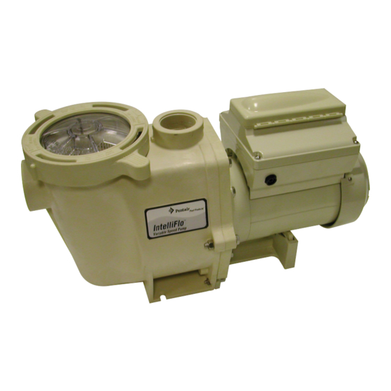
Section 1 Overview IntelliFlo 4 Variable Speed Pump The IntelliFlo 4 variable speed pump is well suited for all of your pool, spa, cleaner, waterfall and other water application. Using the control panel, IntelliFlo can use one of the four selectable preset speeds or the pump speed can be adjusted to run at a specific speed. -
Page 8: Features
• Detects and prevents damage from under and over voltage conditions • Protects against freezing • Communicates with a Pentair IntelliTouch, EasyTouch and IntelliComm system via a two-wire connection • Easy to use operator control panel • Operator control panel buttons for speed control •... -
Page 9: Intelliflo 4 Drive Assembly And Control Panel
IntelliFlo 4 Drive Assembly and Control Panel The IntelliFlo drive assembly consists of an operator control panel and the system electronics that drive the motor. The drive microprocessor controls the motor by changing the frequency of the current it receives together with changing the voltage to control the rotational speed. -
Page 10: Intelliflo 4 Operator Control Panel
IntelliFlo 4 Operator Control Panel The IntelliFlo 4 operator control panel provides manual speed controls for the pump. There are four preset speed buttons that can be selected. The Up and Down button is used to adjust the pump speed. The selected speed can be saved and assigned to one of the speed buttons. -
Page 11: Section 2: Operating Intelliflo 4
Section 2 Operating IntelliFlo 4 This section describes how to use the IntelliFlo 4 pump control panel. Setting the pump preset speed IntelliFlo 4 operates using one of the preset speeds. Use the speed buttons to select the preset speeds. To set the pump speed 1. -
Page 12: Starting The Pump
Starting the pump To start the pump 1. Ensure that the pump is powered on and the green power LED is on. 2. Press the Start button (LED on) to start the pump. Note: When the pump is using a modified speed and is powered down, the next time the pump is powered up, the pump will use that same speed. -
Page 13: Priming The Pump For The First Time Or After Service
Priming the pump for the first time or after service Before the IntelliFlo 4 pump is started for the first time it must be primed. To prime a pump means filling the pump and suction pipe with water. This process evacuates the air from all the suction lines and the pump. It may take several minutes to prime depending on the depth of water, pipe size and length. -
Page 14: Priming The Pump
Priming the pump for the first time or after service (Continued) Priming the Pump • Release all pressure from filter, pump, and piping system; see the filter owner’s manual. • In a flooded suction system (water source higher than pump), the IntelliFlo 4 pump will prime itself when suction and discharge valves are opened. -
Page 15: External Control With Intellicomm Communication Center
External Control with IntelliComm Communication Center The IntelliFlo 4 can be remotely controlled by the Pentair IntelliComm Communication Center using an optional communications cable (P/N 350122). The IntelliComm provides four pairs of input terminal connections. These inputs are actuated by either 15 - 240 VAC or 15 - 100 VDC. Using the device's inputs, the programmed IntelliFlo 4 pump speeds can be controlled. -
Page 16: Connecting Intelliflo 4 To An Easytouch System
Connecting IntelliFlo 4 to an EasyTouch System The IntelliFlo 4 can be controlled by an IntelliTouch system via the RS-485 communication cable (PN 350122). In this configuration, IntelliTouch starts, stops and controls the speed of the IntelliFlo pump. When the IntelliTouch does this, it rewrites the IntelliFlo 4 memory, which can take several seconds. This causes a delay from when a command is given on the IntelliTouch control panel until the Intelliflo 4 physically responds. - Page 17 4. Lower down the hinged control panel to access the EasyTouch motherboard. 5. Route the communication cable into the lower plastic grommet, up through the low voltage raceway to the EasyTouch load center motherboard. Control panel motherboard Low voltage Raceway 6.
- Page 18 9. Close the control panel into its original position and secure it with the two access screws. 10. Install the high voltage cover panel and secure it with the two retaining screws. 11. Close the EasyTouch load center front door. Fasten the two spring latches. 12.
-
Page 19: Section 3: User Maintenance
Section 3 User Maintenance The following information describes how to service and maintain the IntelliFlo pump. Pump Strainer Basket The strainer, sometimes referred to as the “Hair and Lint Pot,” is in front of the of the pump. Inside there is a basket which must be kept clean of leaves and debris at all times. -
Page 20: Motor Service
Pump Strainer Basket Service (Continued) 10. Ensure that the lid o-ring is properly placed. Seat the clamp and lid then turn clockwise until the handles are horizontal as shown. 11. Reconnect the communication cable to the pump if required. 12. Switch the power ON at the circuit breaker. Reset the pool time clock to the correct time. -
Page 21: Winterizing
Winterizing To protect the IntelliFlo 4 pump electronics from damage due to freezing conditions, the pump will switch it self on to generate internal heat when the air temperature drops below 40° F. This feature is not intended to protect the system plumbing from freezing. 1. - Page 22 Blank Page IntelliFlo 4 Installation and User’s Guide...
-
Page 23: Section 4: Installation And Removal
Section 4 Installation and Removal The following information describes how to install the IntelliFlo 4 pump. Note: Before installing this product, read and follow all warning notices and instructions on page ii. IntelliFlo 4 Kit Contents • IntelliFlo 4 160 (or IntelliFlo 4 100) pump Installing the IntelliFlo 4 Only a qualified service person should install the IntelliFlo 4 pump. -
Page 24: Wiring The Intelliflo 4
Wiring the IntelliFlo 4 To connect the IntelliFlo 4 to an AC power source: 1. Make sure all electrical breakers and switches are turned off before wiring motor. 2. Make sure that the wiring voltage is 230 VAC. 3. Use #12 AWG for wire runs up to 100 feet and #10 AWG for lengths longer than 100 feet. When in doubt use a heavier gauge (larger diameter) wire. -
Page 25: Pump Disassembly
Pump Disassembly WARNING — Always disconnect power to the pool pump at the circuit breaker and disconnect the communication cable before servicing the pump. Failure to do so could result in death or serious injury to serviceman, pool users or others due to electric shock. Read all servicing instructions before working on the pump. -
Page 26: Pump Reassembly/Seal Replacement
Pump Disassembly (Continued) 9. To unscrew the impeller from the GASKET shaft, twist the impeller MOTOR counterclockwise. BOLT (4x) SEAL 10. Remove the rotating portion of the O-RING mechanical seal from the impeller. SET SCREW 11. Remove the four bolts from the seal plate to the motor, using a 9/16 inch wrench. -
Page 27: Drive Assembly Removal And Installation
Drive Assembly Removal and Installation To remove the IntelliFlo 4 drive and control panel from the motor assembly: 1. Make sure all electrical breakers and switches are turned off before removing the drive. 2. Disconnect the RS-485 communication cable from the pump. 3. -
Page 28: Illustrated Parts List
Illustrated Parts List 3 15 Replacement Parts 27 30 17 19 12 14 5 9 8 7 18 Item Part Description Item Part Description 070387 BASKET AQ & WF 072184 WASHER 3/8 ID X 7/8 OD .05 THICK 070429 BOLT HEX HD, 2-56x0.875 s/s, 18-8 s/s, (QTY 6) (QTY 4) 072928... -
Page 29: Intelliflo Pump Dimensions
IntelliFlo Pump Dimensions Intelliflo Flow and Power vs Flow Pump Curve IntelliFlo 4 Electrical Specifications Circuit Protection: Two-pole 20 AMP device at the Electrical Panel. Input: 230 VAC, 50/60 Hz, 3200 Watts IntelliFlo 4 Installation and User’s Guide... - Page 30 Blank Page IntelliFlo 4 Installation and User’s Guide...
-
Page 31: Section 5: Troubleshooting
Section 5 Troubleshooting CAUTION: Before installing this product, read and follow all warning notices and instructions on page ii. Warning and Alarm conditions The IntelliFlo 4 alarms and warnings are indicated by flashing LEDs on the control panel. For example, if a “Drive Temperature”... -
Page 32: General Intelliflo 4 Troubleshooting Problems
General IntelliFlo 4 Troubleshooting Problems Use the following general troubleshooting information to resolve possible problems with your IntelliFlo 4 pump. Note: Switch the main power off to the pump before attempting service or repair. l i a l l i d i l d i l . - Page 33 Problems and Corrective Action (Continued) . y l . y t . t l s ’ . t i c i l l i t . f f l l i . y l t t i " " " .
- Page 34 Notes IntelliFlo 4 Installation and User’s Guide...
- Page 36 P/N 357269 - Rev B...
Need help?
Do you have a question about the INTELLIFLO 100 and is the answer not in the manual?
Questions and answers
How many horsepower does the intelli Flo 4 160 have?