Table of Contents
Advertisement
Advertisement
Table of Contents

Subscribe to Our Youtube Channel
Related Manuals for Pentair Sta-rite EnviroMAX 1500


Summary of Contents for Pentair Sta-rite EnviroMAX 1500
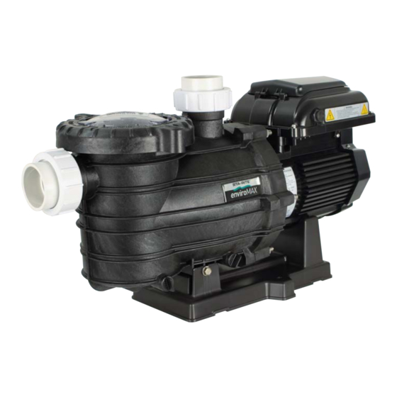
- Page 1 Variable Speed Pool Pump...
- Page 2 Eco Select ® The Eco Select brand identifies our most eco-friendly products ® As the global leader in pool and spa equipment, we’ve made a strong commitment to develop and offer the most environmentally responsible products available. When you see the Eco Select brand on one of our products, you’ll know it is our “greenest”...
-
Page 3: Table Of Contents
Table of Contents Page Features and Benefits Technical Information Model Data Hydraulic Performance Dimensions Installation Pump positioning Piping Pool Outlets Electrical Equipotential Bonding Operation Priming the Pump Control Panel Overview Setting Clock Using Default Schedule Custom Schedules Operating the Pump While Running Quick Clean Keypad Lockout Factory Reset... -
Page 4: Features And Benefits
Features & Benefits The Sta-rite EnviroMAX is the ideal pump for new or existing pools. Utilising advanced hydraulic design and the latest technology in permanent magnet, variable speed motors, the Sta-rite EnviroMAX has the perfect combination of efficiency and performance. The Sta-rite EnviroMAX delivers energy savings and the power when you need it. -
Page 5: Technical Information
Technical Information Model Data RPM: Low 1200RPM Med 2200RPM High 3000RPM Override: 3150RPM Electrical Rating: 230-240V 50Hz single phase Rated Current: Low: 1.0A (max) Med: 3.4A (max) High: 8A (max) Override: 9.6A Motor Input Power (P Low: 188W (max) Med: 750W (max) High: 1840W (max) Override: 2100W Motor Output Power (P... -
Page 6: Hydraulic Performance
Technical Information Hydraulic Performance 100 150 200 250 300 350 400 450 600 650 Flow (L/min) EnviroMAX 1500 Performance Chart Dimensions 661mm 279mm 333mm 385mm 515mm 14.3 ALLOW MINIMUM 364mm CLEARANCE OF 515mm FOR KEYPAD COVER... -
Page 7: Installation
Installation The pump must be installed and serviced by a suitably qualified person in order to avoid hazard. Incorrectly installed or tested equipment may fail, causing severe injury or property damage. These instructions are a guide only. Should you the installer or owner of the product be unfamiliar with the correct installation or operation of this product you should contact a suitably qualified person for advice. -
Page 8: Pool Outlets
Installation 3. Pool Outlets The pump suction system must provide protection against hazard of suction entrapment or hair entrapment/entanglement. The pool outlet piping must be in accordance with the latest AS1926.3 standard Suction outlet covers and skimmers must have been tested and found to comply with the latest AS1926.3 standard or ASME/ANSI specification for Suction Fittings. -
Page 9: Equipotential Bonding
Installation 5. Equipotential bonding If equipotential bonding is required, connect all metal parts of the swimming pool or spa structure and to all electrical equipment, metal conduit, and metal piping in accordance with the wiring rules. Run a wire from the equipotential bonding terminal on the pump (bottom, left motor bolt with serrated washer) to the pool bonding structure. -
Page 10: Operation
Operation NEVER run pump dry. Running pump dry may damage seals, causing leakage and flooding. Fill pump with water before starting motor. Freezing conditions will damage the unit, as water expands as it freezes. Ensure that the EnviroMAX 1500 is located so that it is not prone to freezing, or ensure that the product is disconnected and dried of water during cold conditions. -
Page 11: Control Panel Overview
Operation CONTROL PANEL OVERVIEW Control Panel Overview (4) Display Mode LED Indicators (1) Speed Buttons (5) Display Button (6) Quick Clean (2) External Button Control Only LED Indicator (7) Power LED Indicator (3) Start/Stop Button (8) “+” and “-” Arrows CAUTION If power is connected to the SuperFlo ®... -
Page 12: Setting Clock
Operation Setting the Clock When the pump is first plugged in, the clock will blink to indicate that is has not been set. Any daily schedule set by the user will be based on this clock setting, so it will be necessary to set the clock first. To Set the Clock: 1. -
Page 13: Custom Schedules
Operation Custom Schedules Custom Schedules To customize the run schedule for your SuperFlo ® Press the “ 1” button again and the display will Variable Speed Pump, the pump must be stopped. change to SPEED 1 duration. The “Duration” Custom Schedules To customize the run schedule for your SuperFlo ®... - Page 14 Operation Custom Schedules 7. Use the “+” and “-” arrows to adjust the duration for SPEED 1 in hours and minutes. Note: The duration parameter is adjusted in 15 minute increments. 8. Pressing the “1” button will continue to cycle through these parameters, but the changes are immediately saved as they are adjusted.
-
Page 15: Operating The Pump While Running
Operation Operating the Pump White Running CAUTION If power is connected to the pump motor, pressing any of the following buttons referred to in this section could result in the motor starting. Failure to recognize this could result in personal injury or damage to equipment. Pressing the Display button will cycle through the current parameters. -
Page 16: Keypad Lockout
Priming This pump is shipped with Priming mode ENABLED. Unless the Priming settings are changed in the menu, be aware that the pump will speed up to the priming speed when the pump is powered on for the first time, and the start/stop button is pressed. - Page 17 Key lockout will not prevent the motor from being stopp the Start/Stop button. It will then be unable to be resta keypad has been unlocked. If the motor is operating in Ke mode, and being controlled through external controls, i when the Start/Stop LED is illuminated.
-
Page 18: Factory Reset
Operation Factory Reset The drive can be reset to factory settings if Speed Duration Start Tim necessary. A Factory Reset will wipe out all of the (RPM) (Hours) (Time Cloc Factory Reset saved user settings that have been programmed, SPEED 1 except for the time of day. -
Page 19: External Controls
4. This could be an automation relay or switch in another piece of equipment. This feature could be useful for The wire included with the External Control Wiring Kit (Pentair P/N 353129Z) will need to be cut to length for the ensuring that the pump is running a certain program when a specific speed is needed to perform a task. - Page 20 Operation When using an externally supplied low voltage signal as the Digital Input trigger, the wire should be Using an Externally Supplied Low Voltage Signal for External Control connected as shown in Figure 11. The low voltage input needs to be within the range of 5-30V AC or DC. In When using an externally supplied low voltage signal as the Digital Input trigger, the wire should be connected as this case the red +5V supply from the motor control will not be used.
- Page 21 Call fan. a Pentair Service Agent immediately, to prevent damage to the motor. Check pump and motor for insects and pest infestations and ensure that motor fins are clean of dust and dirt.
-
Page 22: Troubleshooting
Troubleshooting To avoid dangerous or fatal electrical shock hazard, turn OFF power to pump and remove plug from power outlet before working on pump. Troubleshooting guide SYMPTOM CAUSE REMEDY Low water pressure, low Suction leaks / lost prime. ► Pump must be primed; make flow from pump. - Page 23 ► Switch off the power to the pump. the casing and motor. tightened sufficiently; Tighten the casing bolts or replace worn mechanical seal the mechanical seal as required. requires replacing. Should problems persist, contact your nearest Pentair Water Service Agent.
- Page 24 Troubleshooting (Cont.) Problem Possible Cause Corrective Action Pump runs without flow. Impeller is loose Check that pump is spinning by looking at fan on back of SuperFlo VS Variable Speed Pump. If so, check that pump impeller is correctly installed. Troubleshooting Air leak Check plumbing connections and verify they are tight.
- Page 25 Replacement Parts...
- Page 26 Replacement Parts Description Part Number DIFFUSER See Diffuser & O-ring kit DIFFUSER & O-RING KIT (INCLUDES ITEM 1,11&12x7) 801423 IMPELLER 801427 O-RING- COLLAR UNION See Barrel Union Kit COLLAR UNION 2” SLIP See Barrel Union Kit COLLAR UNION 2” See Barrel Union Kit BARREL UNION KIT (INCLUDES 3, 4, &...
- Page 27 Notes...
- Page 28 Email: au.sales@pentair.com Web: www.pentairpool.com.au © Information contained here-in remains the property of Pentair Australia Pty Ltd. Any reproduction, display, publication, modification or distribution is strictly prohibited without the prior written permission of Pentair Australia Pty Ltd. Disclaimer: Every endeavour has been made to publish the correct details in this document. No responsibility will be taken for errors, omissions or changes in product descriptions, specifications.
Need help?
Do you have a question about the Sta-rite EnviroMAX 1500 and is the answer not in the manual?
Questions and answers