
Related Manuals for H3C UAP672X


Summary of Contents for H3C UAP672X
- Page 1 H3C UAP672X Access Point Installation Guide New H3C Technologies Co., Ltd. http://www.h3c.com Document version: 6W100-20231122...
- Page 2 The information in this document is subject to change without notice. All contents in this document, including statements, information, and recommendations, are believed to be accurate, but they are presented without warranty of any kind, express or implied. H3C shall not be liable for technical or editorial errors or omissions contained herein.
- Page 3 Preface This installation guide describes the installation procedure for the H3C UAP672X access point. This preface includes the following topics about the documentation: • Audience. • Conventions. • Documentation feedback. Audience This documentation is intended for: • Network planners. •...
- Page 4 Symbols Convention Description An alert that calls attention to important information that if not understood or followed WARNING! can result in personal injury. An alert that calls attention to important information that if not understood or followed CAUTION: can result in data loss, data corruption, or damage to hardware or software. An alert that calls attention to essential information.
- Page 5 Documentation feedback You can e-mail your comments about product documentation to info@h3c.com. We appreciate your comments.
-
Page 6: Table Of Contents
Contents 1 Preparing for installation ·········································································· 1-1 Examining the installation site ························································································································· 1-1 Installation site selection ························································································································· 1-1 Temperature and humidity requirements ································································································ 1-1 Grounding and lightning protection ········································································································· 1-1 Installation accessories ··································································································································· 1-3 Installation tools ·············································································································································· 1-3 2 Installing the AP ······················································································· 2-1 Pre-installation tasks ·······································································································································... -
Page 7: Preparing For Installation
Preparing for installation WARNING! Install the AP under the guidance of technical engineers and read this chapter carefully before installation. Examining the installation site Examine the installation site before installation to ensure that the AP will work in a good environment. - Page 8 Ground resistance The ground resistance is typically required to be less than 5 ohms, and less than 10 ohms in an area with less than 20 thunderstorm days a year. For a piece of angle steel buried in the earth as a grounding conductor, the ground resistance is required to be less than 10 ohms.
-
Page 9: Installation Accessories
Installation accessories Figure1-1 Installation accessories Installation tools When installing the AP, you might need the following tools. Prepare the installation tools yourself as required. Figure1-2 Installation tools... -
Page 10: Installing The Ap
Installing the AP IMPORTANT: As a best practice to ensure radio coverage, have the AP installed by technical personnel. Pre-installation tasks Before installing an AP, perform the following tasks: • Connect the AP to a power source and the network. Examine the LEDs to verify that the AP can operate correctly. -
Page 11: Installation Flowchart
Installation flowchart Figure2-1 Installation flowchart Start Check before installation Determine the installation position Wall-mount the AP (including connecting Pole-mount the AP (including connecting cables) cables) Connect the AP to a power source Label cables Verify the installation Power on the AP Troubleshoot the AP Operating correctly? Turn off the power switch... -
Page 12: Mounting The Ap
Mounting the AP The AP can be installed only outdoors. You can mount the AP on a wall or a pole. Mounting bracket Figure2-2 Mounting bracket Mounting the AP on a wall Mark the installation holes on the wall based on the installation hole positions in the AP. Figure2-3 Marking the installation holes on the wall Drill four holes with a diameter of 8 mm (0.32 in) and a depth of 30 mm (1.18 in) at the marked locations. - Page 13 Figure2-4 Hammering an expansion bolt into the wall Hang the mounting bracket on the expansion bolts, and then fasten the screws to secure the mounting bracket to the wall. Figure2-5 Securing the mounting bracket to the wall Remove the fastening (grounding) screw on the AP rear and base.
- Page 14 Figure2-6 Removing the fastening (grounding) screw and base Feed the cables (including the Ethernet cable and power cord) through the triangular hole in the base, and then connect the cables to the AP. For how to connect an Ethernet cable and install a liquid-tight adapter, see "Connecting an Ethernet cable."...
- Page 15 Figure2-7 Connecting a cable to the AP Use the fastening (grounding) screw to secure the base and one end of the grounding cable to the AP. Correctly connecting the grounding cable is crucial to lightning protection and EMI protection. Before connect the power cord to the AP, make sure the AP is reliably grounded. For more information, see "Grounding and lightning protection."...
-
Page 16: Mounting The Ap On A Pole
Use M4 screws to secure the device and the other end of the grounding cable to the mounting bracket. Figure2-9 Securing the device and the other end of the grounding cable to the mounting bracket Mounting the AP on a pole For how to connect cables and the grounding cable to the AP and the connection order, see "Mounting the AP on a wall."... - Page 17 Figure2-10 Securing the mounting bracket and clamp brackets to the vertical pole Use M4 screws to secure the AP to the mounting bracket. Figure2-11 Securing the AP to the mounting bracket Mounting the AP on a vertical pole (by using band clamps) The band clamps support poles with a diameter of 60 to 200 mm (2.36 to 7.87 in).
- Page 18 Figure2-12 Securing the mounting bracket to the vertical pole Use M4 screws to secure the AP to the mounting bracket. Figure2-13 Securing the AP to the mounting bracket Mounting the AP on a horizontal pole (by using a mounting bracket) The provided mounting kit supports poles with a diameter of 30 to 60 mm (1.18 to 2.36 in).
- Page 19 Figure2-14 Securing the mounting bracket and clamp brackets to the horizontal pole Use M4 screws to secure the AP to the mounting bracket. Figure2-15 Attaching the AP to the mounting bracket Mounting the AP on a horizontal pole (by using band clamps) The band clamps support poles with a diameter of 60 to 200 mm (2.36 to 7.87 in).
-
Page 20: Connecting An Ethernet Cable
Figure2-16 Securing the mounting bracket to the horizontal pole Use M4 screws to secure the AP to the mounting bracket. Figure2-17 Securing the AP to the mounting bracket Connecting an Ethernet cable CAUTION: To avoid device damage, install weatherproof caps securely for unused ports. 2-11... - Page 21 IMPORTANT: • Only the GE1 port on the AP supports PoE power supply. • Use Category-5e or above Ethernet cables only. As a best practice, use shielded twisted pair (STP) cables. • When you connect an Ethernet cable, do not remove the connector from the AP. Figure2-18 Liquid-tight adapter To connect an Ethernet cable: Disassemble the liquid-tight adapter and put the rubber seal aside, and then feed the cable...
-
Page 22: Connecting The Ap To A Power Source
Figure2-20 Creating a drip loop Connecting the AP to a power source You can supply power to the AP by using a local power source or through 802.3at-compliant PoE. As a best practice, power the AP through PoE. Before powering the AP, make sure the local power source or the 802.3at-compliant power sourcing equipment (PSE) is grounded reliably. -
Page 23: Connecting A Local Power Source
Figure2-21 Connecting the AP to a PoE power source Connecting a local power source CAUTION: To avoid device damage, make sure the weatherproof cap is installed securely on the power port if you do not supply power by using a local power source. Use a power adapter with outdoor lightning protection as the local power source. -
Page 24: Labeling Cables
Figure2-22 Using a power adapter to connect the AP to a local power source Labeling cables After cable connection, attach labels to each cable as a best practice for future maintenance. • Attach a label to both ends of a cable and every certain distance. •... -
Page 25: Connecting The Ap To The Network
Cloudnet App Int. NOTE: • To download and install Cloud App Int, visit https://oasiscloud.h3c.com/ through a browser and use your phone to scan the QR code on the login page. • As a best practice, upgrade Cloud App Int to the most recent version. -
Page 26: Downloading And Installing Cloudnet App Int
Downloading and installing Cloudnet App Int Make sure the smartphone uses Android 4.0, iOS7.0, or a higher-version operating system. Visit https://oasiscloud.h3c.com/ through a browser and use your phone to scan the QR code on the login page to download and install Cloudnet App Int. - Page 27 Contents 1 Appendix A AP view and technical specifications ·································· 1-1 AP view ··························································································································································· 1-1 Technical specifications ·································································································································· 1-1...
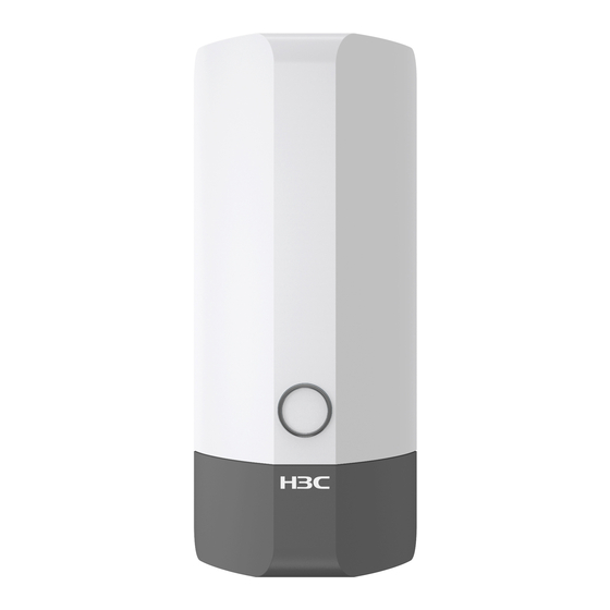
- Page 28 Appendix A AP view and technical specifications AP view Figure1-1 AP view Technical specifications Table1-1 Technical specifications Item Specification Protocol IEEE802.11a/b/g/n/ac/ax Dimensions (H × W × D) 250 × 101 × 110 mm (9.84 × 3.98 × 4.33 in) Weight 1.07 kg (2.36 lb) Built-in omnidirectional antenna: •...
- Page 29 Contents 1 Appendix B LEDs and ports ·································································· 1-1 LEDs ······························································································································································· 1-1 Ports ································································································································································ 1-2...
- Page 30 Appendix B LEDs and ports LEDs Table 1-1 LED descriptions LED status Description No power is present or the LED has been turned off. Steady on The AP is initializing, or an initialization exception has occurred. Yellow Flashing (twice per The Ethernet interfaces are down and no mesh links are second) established.
- Page 31 Ports Figure 1-1 Ports on the AP (1) 10/100/1000M Ethernet port (2) Power port (3) Grounding screw Table 1-2 Port descriptions Standards and Port Description protocols • IEEE802.3 • IEEE802.3ab 10/100/1000M Ethernet copper port, which can receives • PoE power. IEEE802.3i GE1/PoE •...
Need help?
Do you have a question about the UAP672X and is the answer not in the manual?
Questions and answers