Advertisement
Advertisement
Table of Contents

Subscribe to Our Youtube Channel
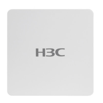
Summary of Contents for H3C UAP672H
- Page 1 H3C UAP672H Access Point Installation Quick Start...
-
Page 2: Installation Tools
Installation tools No installation tools are provided with the AP. Prepare the installation tools yourself as required. PH(2#) Torque Needle-nose Hammer drill Wire stripper screwdriver pliers Handheld Rubber hammer Marker cutting machine Installation accessories M4 screw Wall bracket, (provided) screw anchor, screw (optional) - Page 3 AP/mounting bracket dimensions 8 6 m ( 3 . 3 9 i n ) Mounting the AP on a junction box Do not block the front of the AP at close proximity during use to prevent interference with signal coverage. Connect an Ethernet cable with an RJ-45 connector to the uplink port on the rear of the AP.
-
Page 4: Mounting The Ap On A Wall
1.4N m Mounting the AP on a wall Mark the installation holes for mounting the wall bracket on the wall with a marker. 67 mm (2.64 in) 69.5 mm 30 mm (2.74 in) (2.74 in) Drill holes at the marked locations with an electric drill. Hammer a screw anchor into each hole. -
Page 5: Mounting The Ap On A Ceiling
The wall bracket has side A and side B. Make sure side A faces the wall and determine the direction of the cable hole on the wall bracket based on the wiring direction. Connect an Ethernet cable to the uplink port on the rear of the AP. - Page 6 • After you have removed the ceiling and cut a groove in the ceiling, make the ceiling face down, and then push the AP into the ceiling groove. • The wall bracket has side A and side B. Make sure side B faces the ceiling during installation and determine the direction of the cable hole on the ceiling bracket based on the wiring direction.
- Page 7 LED Status Description Status Description No power is present or the LED has been turned off from the CLI. The AP is initializing, or an Steady on initialization exception has occurred. Slow flashing Yellow No radios have been detected. (once per second) Slow flashing All Ethernet ports are down.
- Page 8 Copyright 2023, New H3C Technologies Co., Ltd. The information in this document is subject to change without notice.


Need help?
Do you have a question about the UAP672H and is the answer not in the manual?
Questions and answers