Miller Syncrowave 250 DX Technical Manual
Hide thumbs
Also See for Syncrowave 250 DX:
- User manual (68 pages) ,
- Owner's manual (68 pages) ,
- Owner's manual (82 pages)
Table of Contents
Advertisement
Visit our website at
www.MillerWelds.com
Syncrowave 250 DX
For the units listed below, use the machine stock number (on rating label) to determine
the correct Technical Manual for service and parts information.
S
Syncrowave 250 DX units with serial numbers LE282983 thru LE468216
Use TM-359 for stock numbers 903726, 903757, 903758, 903759, 903765, 907159.
Use TM-363 for stock numbers 907194, 907195, 907197
.
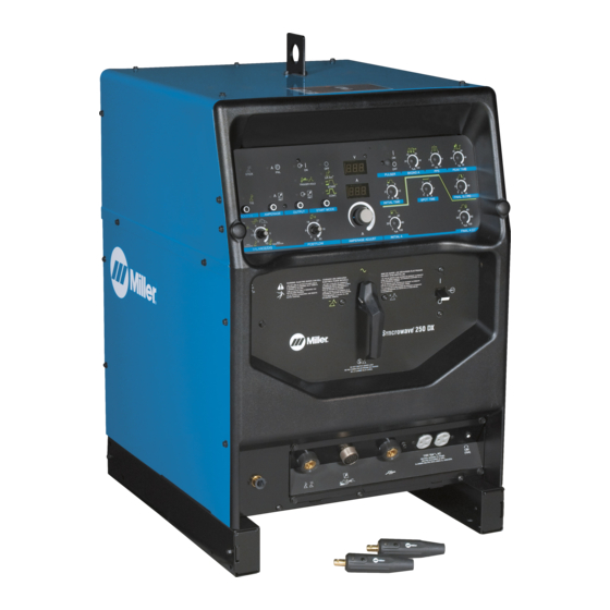
Also verify you are using the correct Technical Manual by comparing the unit to the cover illustration.
TM-359G
Eff. w/Serial Number LA349426
Processes
TIG (GTAW) Welding
Stick (SMAW) Welding
Description
Arc Welding Power Source
R
And Non-Ce Models
File: TIG (GTAW)
2010−03
Advertisement
Table of Contents
Troubleshooting

Related Manuals for Miller Syncrowave 250 DX


Summary of Contents for Miller Syncrowave 250 DX
- Page 1 For the units listed below, use the machine stock number (on rating label) to determine the correct Technical Manual for service and parts information. Syncrowave 250 DX units with serial numbers LE282983 thru LE468216 Use TM-359 for stock numbers 903726, 903757, 903758, 903759, 903765, 907159.
-
Page 2: Table Of Contents
TABLE OF CONTENTS SECTION 1 − SAFETY PRECAUTIONS FOR SERVICING ......... . 1-1. - Page 3 TABLE OF CONTENTS SECTION 5 − THEORY OF OPERATION ............5-1.
- Page 4 European Community (CE) Products NOTE This information is provided for units with CE certification (see rating label on unit). Manufacturer: European Contact: Miller Electric Mg. Co. Mr. Danilo Fedolfi, 1635 W. Spencer St. Managing Director Appleton, WI 54914 USA ITW Welding Products Italy S.r.l.
-
Page 5: Section 1 − Safety Precautions For Servicing
D Do not place unit on, over, or near combustible D Keep away from moving parts such as fans. surfaces. D Keep all doors, panels, covers, and guards D Do not service unit near flammables. closed and securely in place. Syncrowave 250 DX TM-359 Page 1... -
Page 6: California Proposition 65 Warnings
READ INSTRUCTIONS. OVERUSE can cause OVERHEATING. D Use MILLER Testing Booklet (Part No. 150 D Allow cooling period; follow rated duty cycle. 853) when servicing this unit. D Reduce current or reduce duty cycle before D Consult the Owner’s Manual for welding safety... -
Page 7: Section 2 − Definitions
3.2 Welding sparks can cause fires. Have 1.3 Disconnect input plug or power before a fire extinguisher nearby, and have a Do not remove or paint over (cover) working on machine. watchperson ready to use it. the label. 197 310-A Syncrowave 250 DX TM-359 Page 3... -
Page 8: Torch/Cable Holder Label
Do not connect more than one electrode cable to any single weld output terminal. Disconnect cables for process not in use. Have only one welding circuit (process) connected at any given time — never two. 206 345 A TM-359 Page 4 Syncrowave 250 DX... -
Page 9: Symbols And Definitions
Supply Current Electrode Work Thickness Gauge Spark Gap Seconds Final Amperage Initial Time Initial Amperage Pulse Percent On 4 Step Trigger Op- Spot Time Lift-Arct Time eration Sequence Trigger Hold Pulser On-Off Pulse Frequency Syncrowave 250 DX TM-359 Page 5... -
Page 10: Section 3 − Installation
NEC Article 511 or CEC Section 20. Y Be careful when placing or moving unit over uneven surfaces. Location And Airflow 18 in (460 mm) 18 in (460 mm) Ref. 117 264-C / 802 455-C TM-359 Page 6 Syncrowave 250 DX... -
Page 11: Dimensions And Weights
*1.1 *.59 *.29 Cycle NEMA Class II (40) − 16.32 11.81 250 Amperes, 30 With 5 − 310A Volts AC, 40% Duty *55.3 *49.5 *24.5 *19.6 *11.2 *1.93 Cycle *While idling **Power Factor Correction Syncrowave 250 DX TM-359 Page 7... - Page 12 *1.1 *.59 *.29 Cycle NEMA Class II (40) − 14.7 10.1 With 225 Amperes, 29 5 − 310A Volts AC, 40% Duty *55.3 *49.5 *24.5 *19.6 *11.2 *1.93 Cycle *While idling **Power Factor Correction TM-359 Page 8 Syncrowave 250 DX...
-
Page 13: Duty Cycle And Overheating
40% Duty Cycle At 250 Amperes 60% Duty Cycle At 200 Amperes 6 Minutes Welding 4 Minutes Resting 4 Minutes Welding 6 Minutes Resting Overheating Reduce Duty Cycle Minutes duty1 4/95 / 116 198 Syncrowave 250 DX TM-359 Page 9... -
Page 14: Volt-Ampere Curves
The volt-ampere curves show the minimum and maximum voltage and amperage output capabilities of the welding power source. Curves of other settings fall between the curves shown. Non CE Models 194 385-A / 194 384-A TM-359 Page 10 Syncrowave 250 DX... - Page 15 The volt-ampere curves show the minimum and maximum voltage and amperage output capabilities of the welding power source. Curves of other settings fall between the curves shown. CE Models 205 631 / 205 632 Syncrowave 250 DX TM-359 Page 11...
-
Page 16: Weld Output Terminals And Selecting Cable Sizes
0 to +10 volts dc input command signal from remote control. Current feedback; +1 volt dc per 100 amperes. AMPERAGE AMPERAGE Voltage feedback; +1 volt dc per 10 volts output. VOLTAGE Chassis common. Ref. 801 972-C *The remaining sockets are not used. TM-359 Page 12 Syncrowave 250 DX... -
Page 17: Automation 10-Pin Connection (Optional)
Pulse Lockout - output is on when in Initial Amperage, Initial Slope, Final Slope, Final Amperage, and when the pulse frequency is less than 10 Arc On - output is on when the contactor is on and there is less than 50 load volts. Syncrowave 250 DX TM-359 Page 13... -
Page 18: Shielding Gas Connections And 115 Volts Ac Duplex Receptacle
Remote 14 receptacle. Electrode Weld Output Terminal Connect TIG torch to electrode weld outout terminal. Gas Out Connection Connect torch gas hose to gas out fitting. Tools Needed: 11/16, (21 mm), 3/4 in 802 734-C TM-359 Page 14 Syncrowave 250 DX... - Page 19 Notes Syncrowave 250 DX TM-359 Page 15...
-
Page 20: Front Panel Display For Tig Hf Impulse Dcen (Direct Current Electrode Negative)
TIG HF Impulse DCEN welding. For all front panel switch pad controls: press switch pad to turn on light and enable function. NOTE: Green on nameplate indi- cates a TIG function (see Section 4-1 for description of controls). TM-359 Page 16 Syncrowave 250 DX... - Page 21 CE Models Syncrowave 250 DX TM-359 Page 17...
-
Page 22: Front Panel Display For Tig Ac
TIG AC welding. For all front panel switch pad controls: press switch pad to turn on light and enable function. NOTE: Green on nameplate indi- cates a TIG function (see Section 4-1 for description of controls). TM-359 Page 18 Syncrowave 250 DX... - Page 23 CE Models Syncrowave 250 DX TM-359 Page 19...
- Page 24 Notes TM-359 Page 20 Syncrowave 250 DX...
-
Page 25: Stick Connections
Section 3-14. For Stick AC welding, place switch in AC position (see Section 4-2). For Stick AC front panel con- trol dispay, see Section 3-15. Tools Needed: 11/16, (21 mm), 3/4 in 802 733-C Syncrowave 250 DX TM-359 Page 21... -
Page 26: Front Panel Display For Stick Dcep (Direct Current Electrode Positive)
Stick DCEP welding. For all front panel switch pad controls: press switch pad to turn on light and enable function. NOTE: Gray on nameplate indicates a Stick function (see Section 4-1 for description of controls). TM-359 Page 22 Syncrowave 250 DX... - Page 27 CE Models Syncrowave 250 DX TM-359 Page 23...
-
Page 28: Front Panel Display For Stick Ac
Stick AC welding. For all front panel switch pad controls: press switch pad to turn on light and enable function. NOTE: Gray on nameplate indicates a Stick function (see Section 4-1 for description of controls). TM-359 Page 24 Syncrowave 250 DX... - Page 29 CE Models Syncrowave 250 DX TM-359 Page 25...
-
Page 30: Electrical Service Guide
310.16. If a flexible cord or cable is used, minimum conductor size may increase. See NEC Table 400.5(A) for flexible cord and cable requirements. Y Failure to follow these fuse and circuit breaker recommendations could create an electric shock or fire hazard. TM-359 Page 26 Syncrowave 250 DX... -
Page 31: Placing Jumper Links
S-083 566-C Move jumper links to match input voltage. Close and secure access door, or go on to Section 3-18. 230 VOLTS 460 VOLTS 575 VOLTS S-010 587-B Tools Needed: 3/8 in Ref. 801 973-B Syncrowave 250 DX TM-359 Page 27... -
Page 32: Connecting Input Power
Close and secure door on line disconnect de- applicable, use lugs of proper amperage Close and secure access door on welding vice. Remove lockout/tagout device, and capacity and correct hole size. power source. place switch in the On position. TM-359 Page 28 Syncrowave 250 DX... -
Page 33: Section 4 − Operation
See Section 4-5. 14 High Frequency Control Use switch to turn unit Off and On. Start Mode Control (Prior To Serial No LC344556) See Section 4-9. See Section 4-16. 204 776 / Ref. 801 972 Syncrowave 250 DX TM-359 Page 29... - Page 34 See Section 4-5. 14 High Frequency Control Start Mode Control Use switch to turn unit Off and On. (Prior To Serial No LC344556) See Section 4-9. See Section 4-16. 208 242 / Ref. 801 972 TM-359 Page 30 Syncrowave 250 DX...
-
Page 35: Output Selector Switch
For remote amperage control, press button to toggle LED to Re- mote position (see Section 3-7). NOTE: Lit LED indicates selected mode. When Output Selector switch posi- tion changes, LED may change position, based upon last selection. Syncrowave 250 DX TM-359 Page 31... -
Page 36: Output Control
For weld output, press button to toggle LED perage is controlled by the remote device, When Output On is selected, HF and gas to On position. not by the welding power source. control are disabled. TM-359 Page 32 Syncrowave 250 DX... - Page 37 LED to Trigger Hold position. Trigger Hold (2T) can help to reduce op- Torch trigger operation is as shown. NOTE: Amperage is controlled by the erator fatigue. Syncrowave 250 DX TM-359 Page 33...
-
Page 38: 4T Momentary And Mini Logoic Trigger Operation (Requiresoptional Sequence Controls)
Current (A) Weld Amps Final Slope Initial Amps Final Amps Postflow Preflow Push & Release Push & Release Push & Release Push & Release Trigger Trigger Trigger Trigger TM-359 Page 34 Syncrowave 250 DX... - Page 39 Trigger In Less Trigger For More Than 3/4 Sec. Than 3/4 Sec. Than 3/4 Sec. Release Trigger Push & Release Push & Release Trigger In Less Trigger In Less Than 3/4 Sec. Than 3/4 Sec. Syncrowave 250 DX TM-359 Page 35...
-
Page 40: Reconfiguring Trigger Hold For 4T And Mini Logic Control
Proceed to Section 4-6 for 4T Mo- mentary operation. NOTE: These features are only available when optional Sequencer is installed. = 4T Momentary = Mini Logic = 4T (See Section 4-6) (See Section 4-6) (See Section 4-6) H-4E H−4 TM-359 Page 36 Syncrowave 250 DX... - Page 41 (CE Nameplate) Front Panel H−2 = 4T Momentary = Mini Logic = 4T (See Section 4-6) (See Section 4-6) (See Section 4-6) H-4E H−4 Syncrowave 250 DX TM-359 Page 37...
-
Page 42: Selecting Tig Starting Characteristics
Select 3 (high/hot start) − when welding at tion (each position, DCEN, AC, or DCEP has active choice 1= light start, 2=medium/normal high amperages on thick materials with a three applicable start characteristics op- start, 3=high/hot start. large diameter tungsten. TM-359 Page 38 Syncrowave 250 DX... - Page 43 (CE Nameplate) −2− Syncrowave 250 DX TM-359 Page 39...
-
Page 44: Start Mode
Hold High frequency turns on to help start arc NOTE: Some start methods may not be electrode to workpiece for 1-2 sec- when output is enabled. High frequency available for all processes. TM-359 Page 40 Syncrowave 250 DX... -
Page 45: Meters
For pulse welding, use Amperage Adjust control to select from 5−300 amps of peak amperage (see Sec- tion 4-15). For spot welding, use Amperage Adjust control to select from 5−300 amps of peak amperage (see Sec- tion 4-20). Syncrowave 250 DX TM-359 Page 41... -
Page 46: Balance/Dig Control
Application: Control helps arc starting or making vertical or overhead welds by in- creasing amperage at low arc volt- age, and reduces electrode sticking while welding. Ref. S-0795-A TM-359 Page 42 Syncrowave 250 DX... - Page 47 Notes Work like a Pro! Pros weld and cut safely. Read the safety rules at the beginning of this manual. Syncrowave 250 DX TM-359 Page 43...
-
Page 48: Preflow Time Control
Preflow is used to purge the immediate weld Meters play [o.2] [SEL]. The factory preflow default area of atmosphere. Preflow also aids in con- To change preflow time, proceed as follows: setting is 0.2 seconds. To change preflow sistent arc starting. TM-359 Page 44 Syncrowave 250 DX... - Page 49 (CE Nameplate) 00.2 Syncrowave 250 DX TM-359 Page 45...
-
Page 50: Postflow Time Control
Postflow is required to cool tung- sten and weld, and to prevent con- tamination of tungsten and weld. In- crease postflow time if tungsten or weld are dark in appearance (approximately 1 second per 10 ampere of welding current). TM-359 Page 46 Syncrowave 250 DX... -
Page 51: Pulse Controls (Optional)
More Time At input. Controls can be adjusted Background while welding. Amperage Pulsing can also be used for filler (20%) material addition technique training. NOTE: Function is enabled, when LED is lit. Syncrowave 250 DX TM-359 Page 47... -
Page 52: High Frequency Control (Prior To Serial No Lc344556)
See Section 4-18. Initial Amperage Control See Section 4-18. Final Slope Control See Section 4-19. Final Amperage Control See Section 4-19. Spot Time Control See Section 4-20. (CE Nameplate) Ref. 196 616 / Ref. 196 764 TM-359 Page 48 Syncrowave 250 DX... -
Page 53: Initial Time Control And Initial Amperage Control
Initial Amperage can also be used for SMAW to ensure a more consistent arc strike. NOTE: Function is enabled, when LED is lit. Syncrowave 250 DX TM-359 Page 49... -
Page 54: Final Slope Control And Final Amperage Control
TIG spot welding is used for join- ing thinner materials that are in close contact with the fusion method. A good example would be joining coil ends. NOTE: Function is enabled, when LED is lit. TM-359 Page 50 Syncrowave 250 DX... -
Page 55: Timer/Cycle Counter
Output (contactor) buttons while seconds, and are read as 1, 234 hours turning on power. and 56 minutes. and are read as 123, 456 cycles. Syncrowave 250 DX TM-359 Page 51... -
Page 56: Resetting Unit To Factory Default Settings (All Models)
To reset all welding power source functions seconds (or until software version number Output Control to original factory settings, turn power off. _ _ _ _ _ _-_clears meters). Start Control Push and hold the Process, Amperage, TM-359 Page 52 Syncrowave 250 DX... - Page 57 CE Models Syncrowave 250 DX TM-359 Page 53...
-
Page 58: Section 5 − Theory Of Operation
Gas Valve 13 Gas Valve GS1 Remote 14 Pin Automation 10 Pin Receptacle RC1 Receptacle RC3 Provides control of shielding gas. 14 Automation 10-Pin Receptacle RC3 Provides a connection point for op- tional Automation 10-pin. TM-359 Page 54 Syncrowave 250 DX... - Page 59 23 Sloper Control Board PC3 (Optional) Provides user interface for sloper functions. ♦ Pulser Control Board PC2 ♦ Sloper Control Board PC3 AC Or DC Control Circuits 1φ Power Weld Current Circuit ♦ Optional Syncrowave 250 DX TM-359 Page 55...
-
Page 60: Theory Of Operation Effective With Lb141715
12 Gas Valve GS1 Provides control of shielding gas. 13 Automation 10-Pin Receptacle RC3 ♦ Provides a connection point for op- tional Automation 10-pin. Automation 10-Pin Remote 14-Pin Gas Valve Receptacle RC3 Receptacle RC1 TM-359 Page 56 Syncrowave 250 DX... - Page 61 Spark Gaps G Provides user interface for sloper Frequency functions. Capacitor C3 Transformer ♦ Pulser Control Board PC2 ♦ Sloper Control Board PC3 AC Or DC Control Circuits 1φ Power Weld Current Circuit ♦ Optional Syncrowave 250 DX TM-359 Page 57...
-
Page 62: Section 6 − Troubleshooting
6-1. Troubleshooting Table See Section 6-3 or 6-4 for test points and values and Parts List for parts location. Use MILLER Testing Booklet (Part No. 150 853) when servicing this unit. See Section 6-2. Diagnostic help (HLP) messages shown on Voltmeter/Ammeter for help during trouble- shooting. - Page 63 Check wiring of duplex receptacle RC2. Repair or replace if necessary (see Section 6-3). Check main transformer T1 for signs of winding failure. Check continuity across windings, and check for proper connections. Check secondary voltages. Replace T1 if necessary (see Section 6-3). Syncrowave 250 DX TM-359 Page 59...
- Page 64 Shield weld zone from drafts. after conclusion of weld. Increase postflow time (see Section 4-1). Check and tighten all gas fittings (see Section 3-9). Properly prepare tungsten. Replace torch parts if water has leaked into torch. TM-359 Page 60 Syncrowave 250 DX...
- Page 65 Voltage and/or amperage meters not working properly. Check main control board PC1 and connections, and replace if necessary (see Section 6-6). Electronic equipment in welding area not working HF interference problem. Check for proper installation, and correct problem (see Section properly. Syncrowave 250 DX TM-359 Page 61...
-
Page 66: Voltmeter/Ammeter Help Displays
Check to see if pins C and D of the fan to cool it (see Section 3-4). Operation Not used. 10-pin connector are shorted together. −−0 −−1 −−2 −−3 −−4 −−7 −−5 −−6 −−8 −−9 −10 −11 −12 −13 TM-359 Page 62 Syncrowave 250 DX... - Page 67 Notes Syncrowave 250 DX TM-359 Page 63...
-
Page 68: Troubleshooting Circuit Diagram Prior To Serial No. Lb141715
6-3. Troubleshooting Circuit Diagram Prior To Serial No. LB141715 No calibration available for voltmeter V or ammeter A. Y Disable high frequency by placing Mode switch in Off position before testing unit. Test Equipment Needed: See Section 6-6 for PC1 data TM-359 Page 64 Syncrowave 250 DX... - Page 69 All values for T1 are less than 1 ohm Less than 1 ohm 6.1 k ohms 5.1 ohms See Section 6-8 for PC2 information See Section 3-7 See Section 6-10 for RC1 for PC3 data information 202 484-A Syncrowave 250 DX TM-359 Page 65...
-
Page 70: Troubleshooting Circuit Diagram Effective With Serial No. Lb141715
6-4. Troubleshooting Circuit Diagram Effective With Serial No. LB141715 No calibration available for voltmeter V or ammeter A. Y Disable high frequency by placing Mode switch in Off position before testing unit. Test Equipment Needed: See Section 6-6 for PC1 data TM-359 Page 66 Syncrowave 250 DX... - Page 71 All values for T1 are less than 1 ohm Less than 1 ohm 6.1 k ohms 5.1 ohms See Section 6-8 for PC2 information See Section 3-7 See Section 6-10 for RC1 for PC3 data information 194 381-K Syncrowave 250 DX TM-359 Page 67...
-
Page 72: Waveforms For Sections
5 ms 50 V D. 30 Volts AC, 250 Amperes, Arc/Balance C. 30 Volts AC, 250 Amperes, Arc/Balance Con- Control At Max Penetration Position (Re- trol At Max Cleaning Position (Resistive sistive Load) Load) TM-359 Page 68 Syncrowave 250 DX... - Page 73 At Balanced Position (Resistive Load) Balanced Position, Waveform May Not Be Stable 5 ms 1 V G. SCR Gate Pulses With Respect To Cathode At 10 Volts AC, 150 Amperes (Resistive Load) Test Equipment Needed: Syncrowave 250 DX TM-359 Page 69...
-
Page 74: Main (Interface) Board Pc1 Testing Information (Use With Section 6-7)
Receptacle RC2 LED 19 − +15 VDC LED 24 − Backgnd On Receptacle RC3 Receptacle RC4 Receptacle RC5 Receptacle RC6 Receptacle RC7 Receptacle RC9 10 Diagnostic LED’s Test Equipment Needed: 802 839-C / 203 900-D TM-359 Page 70 Syncrowave 250 DX... -
Page 75: Main (Interface) Board Pc1 Test Point Values
Final Time LED, +3.6 volts DC while on, 0 volts DC while off Spot Time LED, +3.6 volts DC while on, 0 volts DC while off Sequencer board PC3 preset, 0 volts DC while connected and +5 volts DC while not connected Syncrowave 250 DX TM-359 Page 71... - Page 76 High frequency control, 115 volts AC when on, 0 volts AC when off Ground reference for 19 volts AC winding 19 volts AC input from transformer T1 19 volts AC input from transformer T1 TM-359 Page 72 Syncrowave 250 DX...
- Page 77 115 volts AC for fans prior to LB141715; 230 volts AC effective with LB141715 Fan-On-Demand control, 115 volts AC while on, 0 volts AC while off prior to LB141715; 230 volts AC effective with LB141715 Machine select, 0 volts dc Ground reference for machine select Syncrowave 250 DX TM-359 Page 73...
-
Page 78: Pulser Board Pc2 Testing Information (Use With Section 6-9)
Pulse Frequency reference, 0 to +5 volts DC variable Pulser LED, +3.6 volts DC while on, 0 volts DC while off Pulser On/Off, 0 volts DC while on; +5 volts DC while off +5 volts DC TM-359 Page 74 Syncrowave 250 DX... -
Page 79: Sloper (Sequencer) Board Pc3 Testing Information (Use With Section 6-11)
6-10. Sloper (Sequencer) Board PC3 Testing Information (Use with Section 6-11) Y Disable high frequency by placing Mode switch in Off position before testing unit. Sloper Board PC3 Plug PLG3 Test Equipment Needed: 802 839-B / 190 739 Syncrowave 250 DX TM-359 Page 75... -
Page 80: Sloper (Sequencer) Board Pc3 Test Point Values
Use output waveforms to check unit output after servicing (see Sec- tion 6-5. Check each module as necessary. If correct voltage is not present, repeat troubleshooting procedures. If removed, reinstall cover and side panels. 801 972−C TM-359 Page 76 Syncrowave 250 DX... -
Page 81: Section 7 − Maintenance
Y Turn off power before reset- ting breaker. Circuit Breaker CB1 If CB1 opens, high frequency and output to the 115 volts ac duplex re- ceptacle stop. Press button to reset breaker. Ref. 801 972-C TM-359 Page 77 Syncrowave 250 DX... -
Page 82: Adjusting Spark Gaps
Apply slight pressure at point until gauge is held firmly in gap. Tighten screws. Adjust other gap. Reinstall access door. Tools Needed: 0.012 in (0.305 mm) 5/32 in Ref. 801 972-C / Ref. S-0043 TM-359 Page 78 Syncrowave 250 DX... -
Page 83: Section 8 − High Frequency
HF or Line Disconnect Device 11 Lighting separate HF unit) Input Supply Wiring 12 Wiring Weld Cables 13 Water Pipes and Fixtures Torch 14 External Phone and Power Lines Work Clamp Workpiece Work Table S-0694 Syncrowave 250 DX TM-359 Page 79... -
Page 84: Correct Installation
A circle 50 ft (15 m) from center point in all 11 Overhead Door Track directions. Grounding Rod Ground the track. Weld Output Cables Consult the National Electrical Code for Keep cables short and close together. specifications. TM-359 Page 80 Syncrowave 250 DX... -
Page 85: Section 9 − Electrical Diagrams
The following is a list of all diagrams for models covered by this manual. Model Serial Or Style Number Circuit Diagram Wiring Diagram Non-CE Syncrowave 250 DX LA349426 Thru LB141714 202 484-A 194 382-B♦♦ LB141715 and following 194 381-K... - Page 86 202 484-A Figure 9-1. Circuit Diagram For Non-CE Syncrowave 250 DX Models Effective With Serial No. LA349426 Thru LB141714 TM-359 Page 82 Syncrowave 250 DX...
- Page 87 194 381-K Figure 9-2. Circuit Diagram For CE Syncrowave 250 DX Models Effective With Serial No. LA349426 Thru LB141714 And All Models Effective With LB141715 And Following Syncrowave 250 DX TM-359 Page 83...
- Page 88 Figure 9-3. Wiring Diagram For Syncrowave 250 DX Effective With Serial No. LA349426 And Following TM-359 Page 84 Syncrowave 250 DX...
- Page 89 194 382-H Syncrowave 250 DX TM-359 Page 85...
- Page 90 Figure 9-4. Circuit Diagram For Main Control Board PC1 Effective With Serial No. LB141715 And Following (Part 1 Of 3) TM-359 Page 86 Syncrowave 250 DX...
- Page 91 203 901-B (1 of 2) Syncrowave 250 DX TM-359 Page 87...
- Page 92 Figure 9-5. Circuit Diagram For Main Control Board PC1 Effective With Serial No. LB141715 And Following (Part 2 Of 3) TM-359 Page 88 Syncrowave 250 DX...
- Page 93 203 901-B (2 of 3) Syncrowave 250 DX TM-359 Page 89...
- Page 94 203 901-B (3 of 3) Figure 9-6. Circuit Diagram For Main Control Board PC1 Effective With Serial No. LB141715 And Following (Part 3 Of 3) TM-359 Page 90 Syncrowave 250 DX...
- Page 95 190 736 Figure 9-7. Circuit Diagram For Optional Pulser Board PC2 Effective With Serial No. LA349426 And Following Syncrowave 250 DX TM-359 Page 91...
- Page 96 Figure 9-8. Circuit Diagram For Main Control Board PC1 With Optional Automation 10-Pin Connection Effective With Serial No. LB141715 And Following (Part 1 Of 3) TM-359 Page 92 Syncrowave 250 DX...
- Page 97 203 923-A Syncrowave 250 DX TM-359 Page 93...
- Page 98 Figure 9-9. Circuit Diagram For Main Control Board PC1 With Optional Automation 10-Pin Connection Effective With Serial No. LB141715 And Following (Part 2 Of 3) TM-359 Page 94 Syncrowave 250 DX...
- Page 99 203 923-A Syncrowave 250 DX TM-359 Page 95...
- Page 100 203 923-A Figure 9-10. Circuit Diagram For Main Control Board PC1 With Optional Automation 10-Pin Connection Effective With Serial No. LB141715 And Following (Part 3 Of 3) TM-359 Page 96 Syncrowave 250 DX...
- Page 101 190 740 Figure 9-11. Circuit Diagram For Optional Sloper Board PC3 Effective With Serial No. LA349426 And Following Syncrowave 250 DX TM-359 Page 97...
-
Page 102: Section 10 − Selecting And Preparing Tungsten Electrode For Dc Or Ac Welding
Typical argon shielding gas flow rates are 15 to 35 cfh (cubic feet per hour). *Not Recommended. Figures listed are a guide and are a composite of recommendations from American Welding Society (AWS) and electrode manufacturers. TM-359 Page 98 Syncrowave 250 DX... -
Page 103: Preparing Tungsten Electrode For Welding
Ball end of tungsten by applying AC amperage recommended for a giv- 1 − 1-1/2 Times en electrode diameter (see Section Electrode Diameter 10-1). Let ball on end of the tung- sten take its own shape. Syncrowave 250 DX TM-359 Page 99... -
Page 104: Section 11 − Guidelines For Tig Welding (Gtaw)
The tungsten extension should be no greater than the inside diameter of the gas cup. Arc length is the distance from the tungsten to the workpiece. 1/16 in 3/16 in Bottom View Of Gas Cup Ref. ST-161 892 TM-359 Page 100 Syncrowave 250 DX... -
Page 105: Torch Movement During Welding
Move torch to front of pool. Repeat process. Tungsten With Filler Rod ° ° Welding direction Form pool Tilt torch Add filler metal Remove rod Move torch to front of pool. Repeat process. ST-162 002-B Syncrowave 250 DX TM-359 Page 101... -
Page 106: Positioning Torch Tungsten For Various Weld Joints
11-3. Positioning Torch Tungsten For Various Weld Joints ° Butt Weld And Stringer Bead ° ° ° “T” Joint ° ° ° ° 20-40 Lap Joint ° ° ° ° Corner Joint ° ° ST-162 003 / S-0792 TM-359 Page 102 Syncrowave 250 DX... -
Page 107: Section 12 − Stick Welding (Smaw) Guidelines
Slag Use a chipping hammer and wire brush to remove slag. Remove slag and check weld bead before mak- ing another weld pass. Tools Needed: stick 12/96 − ST-151 593 Syncrowave 250 DX TM-359 Page 103... - Page 108 Bring electrode straight down to workpiece; then lift slightly to start arc. If arc goes out, electrode was lifted too high. If electrode sticks to workpiece, use a quick twist to free it. S-0050 TM-359 Page 104 Syncrowave 250 DX...
- Page 109 12-7. Good Weld Bead Characteristics Fine Spatter Uniform Bead Moderate Crater During Welding Weld a new bead or layer for each 1/8 in. (3.2 mm) thickness in metals being welded. No Overlap Good Penetration into Base Metal S-0052-B Syncrowave 250 DX TM-359 Page 105...
- Page 110 Weave Bead − Side to Side Movement Along Seam Weave Patterns Use weave patterns to cover a wide area in one pass of the electrode. Do not let weave width exceed 2-1/2 times diameter of electrode. S-0054-A TM-359 Page 106 Syncrowave 250 DX...
- Page 111 Multi-Layer Deposits Weld a second layer when a heavi- er fillet is needed. Use any of the weaving patterns shown in Section 12-9. Remove slag before making another weld pass. S-0060 / S-0058-A / S-0061 Syncrowave 250 DX TM-359 Page 107...
- Page 112 Possible Causes Corrective Actions Amperage too high for electrode. Decrease amperage or select larger electrode. Arc length too long or voltage too high. Reduce arc length or voltage. TM-359 Page 108 Syncrowave 250 DX...
- Page 113 Excessive Penetration − weld metal melting through base metal and hanging underneath weld. Excessive Penetration Good Penetration Possible Causes Corrective Actions Excessive heat input. Select lower amperage. Use smaller electrode. Increase and/or maintain steady travel speed. Syncrowave 250 DX TM-359 Page 109...
- Page 114 Use restraint (clamp) to hold base metal in position. Make tack welds along joint before starting welding operation. Select lower amperage for electrode. Increase travel speed. Weld in small segments and allow cooling between welds. TM-359 Page 110 Syncrowave 250 DX...
- Page 115 TM-359G 2006−01 Eff. w/Serial Number LA349426 Processes TIG (GTAW) Welding Stick (SMAW) Welding Description Arc Welding Power Source Syncrowave 250 DX Eff w/ LA349426 Through LC066672 And Non-Ce Models Visit our website at www.MillerWelds.com...
-
Page 116: Section 13 − Parts List La349426 Thru Lc066672
SECTION 13 − PARTS LIST LA349426 Thru LC066672 Hardware is common and not available unless listed. 802 609-E Figure 13-1. Main Assembly TM-359 Page 112 Syncrowave 250 DX... - Page 117 ..... . 194 590 . . . Label, Miller 12.563 X 5.376 Horizontal Syncrowav ....
- Page 118 ....196 766 . . . Nameplate, Miller Syncrowave 250DX (Wordless) ....
- Page 119 To maintain the factory original performance of your equipment, use only Manufacturer’s Suggested Replacement Parts. Model and serial number required when ordering parts from your local distributor. Hardware is common and not available unless listed. Figure 13-2. HF Control Box Assembly 802 756-A Syncrowave 250 DX TM-359 Page 115...
- Page 120 To maintain the factory original performance of your equipment, use only Manufacturer’s Suggested Replacement Parts. Model and serial number required when ordering parts from your local distributor. Hardware is common and not available unless listed. 802 757 Figure 13-3. HF Panel Assembly, Lower TM-359 Page 116 Syncrowave 250 DX...
- Page 121 To maintain the factory original performance of your equipment, use only Manufacturer’s Suggested Replacement Parts. Model and serial number required when ordering parts from your local distributor. Hardware is common and not available unless listed. Ref. 802 609-A Figure 13-4. Rectifier Assembly Syncrowave 250 DX TM-359 Page 117...
- Page 122 Notes TM-359 Page 118 Syncrowave 250 DX...
- Page 123 TM-359G 2006−01 Eff. w/Serial Number LA349426 Processes TIG (GTAW) Welding Stick (SMAW) Welding Description Arc Welding Power Source Syncrowave 250 DX Eff w/ LC066673 And Following And Non-Ce Models Visit our website at www.MillerWelds.com...
-
Page 124: Section 14 − Parts List For Lc066672 And Following
SECTION 14 − PARTS LIST FOR LC066672 AND FOLLOWING Hardware is common and not available unless listed. 802 609-L Figure 14-1. Main Assembly TM-359 Page 120 Syncrowave 250 DX... - Page 125 ....194 590 . . . Label, Miller 12.563 X 5.376 Horizontal Syncrowav ....
- Page 126 ....208 242 . . . Nameplate, Miller Syncrowave 250DX (Wordless) ....
- Page 127 To maintain the factory original performance of your equipment, use only Manufacturer’s Suggested Replacement Parts. Model and serial number required when ordering parts from your local distributor. Hardware is common and not available unless listed. 803 165-B Figure 14-2. HF Panel Assembly, Lower Syncrowave 250 DX TM-359 Page 123...
- Page 128 To maintain the factory original performance of your equipment, use only Manufacturer’s Suggested Replacement Parts. Model and serial number required when ordering parts from your local distributor. Hardware is common and not available unless listed. 803 164-A Figure 14-3. Rectifier Assembly TM-359 Page 124 Syncrowave 250 DX...
- Page 129 Notes...
- Page 130 Appleton, WI 54914 USA International Headquarters−USA USA Phone: 920-735-4505 Auto-Attended USA & Canada FAX: 920-735-4134 International FAX: 920-735-4125 European Headquarters − United Kingdom Phone: 44 (0) 1204-593493 FAX: 44 (0) 1204-598066 © PRINTED IN USA 2006 Miller Electric Mfg. Co.
Need help?
Do you have a question about the Syncrowave 250 DX and is the answer not in the manual?
Questions and answers