Sign In
Upload
Manuals
Brands
Miller Manuals
Welding System
Syncrowave 250 DX
Miller Syncrowave 250 DX Manuals
Manuals and User Guides for Miller Syncrowave 250 DX. We have
4
Miller Syncrowave 250 DX manuals available for free PDF download: Technical Manual, Owner's Manual, User Manual
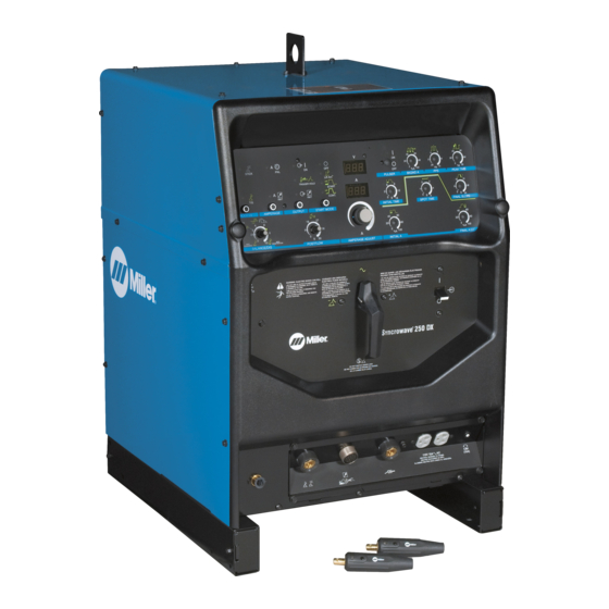
Miller Syncrowave 250 DX Technical Manual (130 pages)
Brand:
Miller
| Category:
Welding System
| Size: 5 MB
Table of Contents
Table of Contents
2
Section 1 − Safety Precautions for Servicing
5
Symbol Usage
5
Servicing Hazards
5
California Proposition 65 Warnings
6
EMF Information
6
Section 2 − Definitions
7
Warning Label Definitions
7
Torch/Cable Holder Label
8
Weld Cable Connection Label
8
Symbols and Definitions
9
Section 3 − Installation
10
Selecting a Location
10
Dimensions and Weights
11
Specifications
11
Duty Cycle and Overheating
13
Volt-Ampere Curves
14
Weld Output Terminals and Selecting Cable Sizes
16
Remote 14 Receptacle Information
16
Automation 10-Pin Connection (Optional)
17
Shielding Gas Connections and 115 Volts AC Duplex Receptacle
18
TIG Connections
18
Front Panel Display for TIG HF Impulse DCEN (Direct Current Electrode Negative)
20
Front Panel Display for TIG AC
22
Stick Connections
25
Front Panel Display for Stick DCEP (Direct Current Electrode Positive)
26
Front Panel Display for Stick AC
28
Electrical Service Guide
30
Placing Jumper Links
31
Connecting Input Power
32
Section 4 − Operation
33
Controls
33
Output Selector Switch
35
Process Control
35
Amperage Control
35
Output Control
36
4T Momentary and Mini Logoic Trigger Operation (Requiresoptional Sequence Controls)
38
Reconfiguring Trigger Hold for 4T and Mini Logic Control
40
Selecting TIG Starting Characteristics
42
Start Mode
44
Meters
45
Amperage Adjustment Control
45
Balance/Dig Control
46
Preflow Time Control
48
Postflow Time Control
50
Pulse Controls (Optional)
51
High Frequency Control (Prior to Serial no LC344556)
52
Sequence Controls (Optional)
52
Initial Time Control and Initial Amperage Control
53
Final Slope Control and Final Amperage Control
54
Spot Time Control
54
Timer/Cycle Counter
55
Resetting Unit to Factory Default Settings (All Models)
56
Section 5 − Theory of Operation
58
Theory of Operation Prior to LB141715
58
Theory of Operation Effective with LB141715
60
Section 6 − Troubleshooting
62
Troubleshooting Table
62
Voltmeter/Ammeter Help Displays
66
Troubleshooting Circuit Diagram Prior to Serial No. LB141715
68
Troubleshooting Circuit Diagram Effective with Serial No. LB141715
70
Waveforms for Sections
72
Main (Interface) Board PC1 Testing Information (Use with Section 6-7)
74
Main (Interface) Board PC1 Test Point Values
75
Pulser Board PC2 Testing Information (Use with Section 6-9)
78
Pulser Board PC2 Test Point Values
78
Sloper (Sequencer) Board PC3 Testing Information (Use with Section 6-11)
79
Sloper (Sequencer) Board PC3 Test Point Values
80
Check Unit Output after Servicing
80
Section 7 − Maintenance
81
Routine Maintenance
81
Circuit Breaker CB1
81
Adjusting Spark Gaps
82
Section 8 − High Frequency
83
Welding Processes Requiring High Frequency
83
Incorrect Installation
83
Correct Installation
84
Section 9 − Electrical Diagrams
85
Section 10 − Selecting and Preparing Tungsten Electrode for DC or Ac Welding
102
Selecting Tungsten Electrode (Wear Clean Gloves to Prevent Contamination of Tungsten)
102
Preparing Tungsten Electrode for Welding
103
Section 11 − Guidelines for Tig Welding (Gtaw)
104
Positioning the Torch
104
Torch Movement During Welding
105
Positioning Torch Tungsten for Various Weld Joints
106
Section 12 − Stick Welding (Smaw) Guidelines
107
SECTION 13 − PARTS LIST LA349426 Thru LC066672
116
Section 14 − Parts List for Lc066672 and Following
124
Advertisement
Miller Syncrowave 250 DX Owner's Manual (82 pages)
CE And Non-CE Model
Brand:
Miller
| Category:
Welding System
| Size: 4 MB
Table of Contents
Table of Contents
3
Section 1 − Safety Precautions - Read before Using
7
Symbol Usage
7
Arc Welding Hazards
7
Additional Symbols for Installation, Operation, and Maintenance
9
California Proposition 65 Warnings
10
Principal Safety Standards
10
EMF Information
10
Section 2 − Definitions
11
Warning Label Definitions
11
WEEE Label (for Products Sold Within the EU)
11
Symbols and Definitions
12
Section 3 − Installation
13
Serial Number and Rating Label Location
13
Selecting a Location
13
Dimensions and Weights
14
Cooler Specifications
14
Welding Power Source Specifications
14
Duty Cycle and Overheating
16
Volt-Ampere Curves
17
Weld Output Terminals and Selecting Cable Sizes
19
Remote 14 Receptacle Information
20
Shielding Gas Connections and 115 Volts AC Duplex Receptacle
20
TIG Connections with a Two-Piece Air-Cooled Torch
21
TIG Connections with a One-Piece Air-Cooled Torch
21
Front Panel Display for TIG HF Impulse DCEN (Direct Current Electrode Negative)
22
Front Panel Display for TIG AC
23
Optional Cooler Connections
24
Stick Connections
25
Front Panel Display for Stick DCEP (Direct Current Electrode Positive)
26
Front Panel Display for Stick AC
27
Electrical Service Guide
28
Placing Jumper Links
30
Connecting Input Power
31
Section 4 − Operation
32
Controls (350 LX Nameplates Shown)
32
Output Selector Switch
34
Process Control
34
Amperage Control
34
Output Control
36
4T Momentary, and Mini Logoic Trigger Operation (Requires Optional Sequence Controls)
38
Reconfiguring Trigger Hold for 4T and Mini Logic Control
40
Selecting TIG Starting Characteristics Using Syncro-Startt Technology
42
Start Mode
44
Balance/Dig Control
45
Preflow Time Control
46
Pulse Controls (Standard on 350 LX Models, Optional on 250 DX Models)
48
Sequence Controls (Optional)
49
Initial Time Control and Initial Amperage Control
50
Final Slope Control and Final Amperage Control
51
Spot Time Control
51
Timer/Cycle Counter
52
Resetting Unit to Factory Default Settings (All Models)
53
Section 5 − Maintenance
54
Routine Welding Power Source Maintenance
54
Routine Maintenance
54
Circuit Breaker CB1
54
Adjusting Spark Gaps
55
Section 6 − Troubleshooting
56
Voltmeter/Ammeter Help Displays
56
Troubleshooting the Welding Power Source
57
Routine Maintenance for Optional Cooler
58
Troubleshooting the Optional Cooler
58
Coolant Maintenance and Oiling Motor
59
Section 7 − Electrical Diagram
60
Section 8 − High Frequency
63
Welding Processes Requiring High Frequency
63
Incorrect Installation
63
Correct Installation
64
Section 9 − Selecting and Preparing a Tungsten for DC or Ac Welding
65
Selecting Tungsten Electrode (Wear Clean Gloves to Prevent Contamination of Tungsten)
65
Preparing Tungsten Electrode for Welding with Phase Control Machines
65
Section 10 − Guidelines for Tig Welding (Gtaw)
66
Positioning the Torch
66
Torch Movement During Welding
67
Positioning Torch Tungsten for Various Weld Joints
68
Section 11 − Parts List
70
Section 12 − Parts List for Optional Cooler
78
Options and Accessories
82
Miller Syncrowave 250 DX User Manual (68 pages)
Arc Welding Power Source With Optional Running Gear And Cooler
Brand:
Miller
| Category:
Welding System
| Size: 3 MB
Table of Contents
Table of Contents
3
FOR ADDITIONAL WELDING INFORMATION and RESOURCES, VISIT: Www.millerwelds.com
5
Section 1 − Safety Precautions - Read before Using
5
Symbol Usage
5
Arc Welding Hazards
5
Additional Symbols for Installation, Operation, and Maintenance
7
California Proposition 65 Warnings
8
Principal Safety Standards
8
EMF Information
8
Section 2 − Consignes de Sécurité − Lire Avant Utilisation
9
Symboles Utilisés
9
Dangers Relatifs Au Soudage À L'arc
9
Dangers Supplémentaires en Relation Avec L'installation, Le Fonctionnement Et la Maintenance
11
Proposition Californienne 65 Avertissements
12
Principales Normes de Sécurité
13
Informations Relatives Aux CEM
13
Section 3 − Definitions
15
Warning Label Definitions
15
WEEE Label
15
Symbols and Definitions
16
Section 4 − Installation
17
Important Information Regarding IEC Products
17
Serial Number and Rating Label Location
17
Selecting a Location
18
Dimensions and Weights
19
Cooler Specifications
19
Welding Power Source Specifications
19
Duty Cycle and Overheating
21
Volt-Ampere Curves
22
Weld Output Terminals and Selecting Cable Sizes
23
Remote 14 Receptacle Information
24
Shielding Gas Connections and 115 Volts AC Duplex Receptacle
24
TIG Connections with a Two-Piece Air-Cooled Torch
25
TIG Connections with a One-Piece Air-Cooled Torch
25
Front Panel Display for TIG HF Impulse DCEN (Direct Current Electrode Negative)
26
Front Panel Display for TIG AC
27
Optional Cooler Connections
28
Stick Connections
29
Front Panel Display for Stick DCEP (Direct Current Electrode Positive)
30
Front Panel Display for Stick AC
31
Electrical Service Guide
32
Placing Jumper Links
34
Connecting Input Power
35
Section 5 − Operation
36
Controls (350 LX Nameplates Shown)
36
Output Selector Switch
37
Process Control
37
Amperage Control
37
Output Control
38
4T Momentary, and Mini Logic Trigger Operation (Requires Optional Sequence Controls)
40
Reconfiguring Trigger Hold for 4T and Mini Logic Control
42
Selecting TIG Starting Characteristics Using Syncro-Startt Technology
43
Start Mode
44
Balance/Dig Control
45
Preflow Time Control
46
Pulse Controls (Standard on 350 LX Models, Optional on 250 DX Models)
47
Sequence Controls (Optional)
48
Initial Time Control and Initial Amperage Control
48
Final Slope Control and Final Amperage Control
49
Spot Time Control
49
Timer/Cycle Counter
50
Resetting Unit to Factory Default Settings (All Models)
51
Section 6 − Maintenance
52
Routine Welding Power Source Maintenance
52
Supplementary Protector CB1
52
Adjusting Spark Gaps
53
Routine Maintenance for Optional Cooler
53
Coolant Maintenance
54
Section 7 − Troubleshooting
55
Voltmeter/Ammeter Help Displays
55
Troubleshooting the Welding Power Source
56
Troubleshooting the Optional Cooler
57
Section 8 − Parts List
57
Recommended Spare Parts
57
Section 9 − Electrical Diagram
58
Section 10 − High Frequency
61
Welding Processes Requiring High Frequency
61
Installation Showing Possible Sources of HF Interference
61
Recommended Installation to Reduce HF Interference
62
Section 11 − Selecting and Preparing a Tungsten for DC or Ac Welding
63
Selecting Tungsten Electrode (Wear Clean Gloves to Prevent Contamination of Tungsten)
63
Preparing Tungsten Electrode for Welding with Phase Control Machines
63
Options and Accessories
68
Advertisement
Miller Syncrowave 250 DX Owner's Manual (68 pages)
With Optional Running Gear And Cooler
Brand:
Miller
| Category:
Welding System
| Size: 2 MB
Table of Contents
Table of Contents
3
Section 1 − Safety Precautions - Read before Using
5
Symbol Usage
5
Arc Welding Hazards
5
Additional Symbols for Installation, Operation, and Maintenance
7
California Proposition 65 Warnings
8
Principal Safety Standards
8
EMF Information
8
Section 2 − Consignes de Sécurité − Lire Avant Utilisation
9
Symboles Utilisés
9
Dangers Relatifs Au Soudage À L'arc
9
Dangers Supplémentaires en Relation Avec L'installation, Le Fonctionnement Et la Maintenance
11
Proposition Californienne 65 Avertissements
13
Principales Normes de Sécurité
13
Informations Relatives Aux CEM
13
Section 3 − Definitions
15
Additional Safety Symbols and Definitions
15
Miscellaneous Symbols and Definitions
16
Section 4 − Specifications
18
Serial Number and Rating Label Location
18
Cooler Specifications
18
Welding Power Source Specifications
18
Duty Cycle and Overheating
20
Volt-Ampere Curves
21
Dimensions and Weights
22
Environmental Specifications
22
Section 5 − Installation
23
Selecting a Location
23
Weld Output Terminals and Selecting Cable Sizes
24
Weld Output Terminals
24
Remote 14 Receptacle Information
25
Shielding Gas Connections and 115 Volts AC Cooler Receptacle
25
TIG Connections with a Two-Piece Air-Cooled Torch
26
TIG Connections with a One-Piece Air-Cooled Torch
26
Front Panel Display for TIG HF Impulse DCEN (Direct Current Electrode Negative)
27
Front Panel Display for TIG AC
28
Optional Cooler Connections
29
Stick Connections
30
Front Panel Display for Stick DCEP (Direct Current Electrode Positive)
31
Front Panel Display for Stick AC
32
Electrical Service Guide
33
Placing Jumper Links
35
Connecting Input Power
36
Section 6 − Operation
38
Controls (350 LX Nameplates Shown)
38
Output Selector Switch
39
Process Control
39
Amperage Control
39
Output Control
40
4T Momentary, and Mini Logic Trigger Operation (Requires Optional Sequence Controls)
42
Reconfiguring Trigger Hold for 4T and Mini Logic Control
44
Selecting TIG Starting Characteristics Using Syncro-Startt Technology
45
Start Mode
46
Balance/Dig Control
47
Preflow Time Control
48
Pulse Controls (Standard on 350 LX Models, Optional on 250 DX Models)
49
Sequence Controls (Optional)
50
Initial Time Control and Initial Amperage Control
50
Final Slope Control and Final Amperage Control
51
Spot Time Control
51
Timer/Cycle Counter
52
Resetting Unit to Factory Default Settings (All Models)
53
Section 7 − Maintenance
54
Routine Welding Power Source Maintenance
54
Supplementary Protector CB1
54
Adjusting Spark Gaps
55
Routine Maintenance for Optional Cooler
55
Coolant Maintenance
56
Section 8 − Troubleshooting
57
Voltmeter/Ammeter Help Displays
57
Troubleshooting the Welding Power Source
58
Troubleshooting the Optional Cooler
59
Section 9 − Parts List
59
Recommended Spare Parts
59
Section 10 − Electrical Diagram
60
Section 11 − High Frequency
63
Welding Processes Requiring High Frequency
63
Installation Showing Possible Sources of HF Interference
63
Recommended Installation to Reduce HF Interference
64
Section 12 − Selecting and Preparing a Tungsten for DC or Ac Welding
65
Selecting Tungsten Electrode (Wear Clean Gloves to Prevent Contamination of Tungsten)
65
Preparing Tungsten Electrode for Welding with Phase Control Machines
65
Options and Accessories
68
Advertisement
Related Products
Miller Millermatic 250X
Miller Millermatic 250MP
Miller MIGMATIC 250
Miller MigMatic 250 Base
Miller matic 250mp 1995
Miller Dialarc 250 AC/DC
Miller Dialarc 250P AC/DC
Miller Trailblazer 251
Miller Millermatic 255
Miller XR-Aluma-Pro 25W
Miller Categories
Welding System
Welding Accessories
Camera Accessories
Portable Generator
Motorcycle Accessories
More Miller Manuals
Login
Sign In
OR
Sign in with Facebook
Sign in with Google
Upload manual
Upload from disk
Upload from URL