Table of Contents
Troubleshooting

Related Manuals for Miller XR-A Python 25 Ft.


Summary of Contents for Miller XR-A Python 25 Ft.
- Page 1 OM-1500-17 218 022G 2006−06 Processes MIG (GMAW) Welding Description Semi-Automatic, Air-Cooled, MIG (GMAW) Welding Gun ™ XR -A Python 25 Ft. ® 200 Ampere Push-Pull Welding Gun File: MIG (GMAW) Visit our website at www.MillerWelds.com...
- Page 2 We know you don’t have time to do it any other way. That’s why when Niels Miller first started building arc welders in 1929, he made sure his products offered long-lasting value and superior quality.
-
Page 3: Table Of Contents
TABLE OF CONTENTS SECTION 1 −SAFETY PRECAUTIONS FOR GMAW WELDING GUNS − READ BEFORE USING ..1-1. Symbol Usage ............... . 1-2. - Page 4 European Community (CE) Products NOTE This information is provided for units with CE certification (see rating label on unit). Manufacturer: European Contact: Miller Electric Mg. Co. Mr. Danilo Fedolfi, 1635 W. Spencer St. Managing Director Appleton, WI 54914 USA ITW Welding Products Italy S.r.l.
-
Page 5: Section 1 −Safety Precautions For Gmaw Welding Guns − Read Before Using
SECTION 1 −SAFETY PRECAUTIONS FOR GMAW WELDING GUNS − READ BEFORE USING SR7_8/03 1-1. Symbol Usage Y Marks a special safety message. Means Warning! Watch Out! There are possible hazards with this procedure! The possible hazards are shown in the adjoining symbols. Means NOTE;... -
Page 6: Emf Information
EMF INFORMATION NOTE Considerations About Welding And The Effects Of Low Frequency Electric And Magnetic Fields The following is a quotation from the General Conclusions Section of To reduce magnetic fields in the workplace, use the following procedures: the U.S. Congress, Office of Technology Assessment, Biological Effects of Power Frequency Electric &... -
Page 7: Section 2 − Definitions
SECTION 2 − DEFINITIONS 2-1. Warning Label Definitions A. Warning! Watch Out! There are possible hazards as shown by the symbols. B. Drive rolls can injure fingers. C. Welding wire and drive parts are at welding voltage during operation − keep hands and metal objects clear. -
Page 8: Symbols And Definitions
2-2. Symbols And Definitions Note Some symbols are found only on CE products. Amperes Volts Alternating Current Duty Cycle Degree Of Hertz Circuit Breaker Wire Feed Protection Output Trigger Press To Set Increase Trigger Hold On Trigger Hold Off Purge Spot Weld Time Percent Run-In... -
Page 9: Section 3 − Installation
SECTION 3 − INSTALLATION 3-1. Specifications Wire Capacity Aluminum wire - .030 in - 1/16 in (0.8 mm - 1.6 mm) using teflon liner Cored and Hard wire - .030 in - .045 in (0.6 mm - 1.2 mm) using spiral steel liner Wire Speed At rated feeder input voltage - 70-800 Ipm (20.3 mpm) Duty Cycle - 100% (200 Amps peak) -
Page 10: Section 4 − Operation
SECTION 4 − OPERATION 4-1. Controls and Settings Potentiometer The potentiometer is located in the lower end of the handle, providing up to 800 ipm (20.3 mpm) with 3 3/4 turns. Trigger Trigger Sensitivity Adjustment Screw The amount of trigger level travel can be shortened for quicker re- sponse action. -
Page 11: Drive Roll Removal/Installation
4-2. Drive Roll Removal/Installation Drive Roll Removal Tool P/N 215676 Drive Roll Idler Roll Cam Lever The gun handles do not need to be removed for access to the drive or idler rolls. Drive Roll Removal/Installation For insulated drive roll kits see Section 8 Options and Acces- sories. -
Page 12: Idler Roll Removal/Installation
4-3. Idler Roll Removal/Installation Idler Roll Lockwasher Idler Arm Spring Idler Screw The gun handles do not need to be removed for access to the drive or idler rolls. Idler Roll Removal/Installation Using a slot type screwdriver, loosen idler screw, taking care not to lose lock washer under idler roll. -
Page 13: Section 5 − Maintenance & Troubleshooting
SECTION 5 − MAINTENANCE & TROUBLESHOOTING 5-1. Routine Maintenance Y Disconnect power Maintain more often before maintaining. during severe conditions. Each Spool Of Wire Clean Nozzle Blow Out Gun And Check Casing and Conduit Contact Tip 3 Months Clean And Replace Tighten Damaged Or... -
Page 14: Troubleshooting Table
5-3. Troubleshooting Table Y Disconnect power before troubleshooting. Trouble Remedy Reset circuit breaker in feeder/control box. See feeder/control owner’s manual. No wire feed at gun, feeder not operat- ing Check motor or brake solenoid ing. Check motor or brake solenoid. Replace micro-switch and test operation. -
Page 15: Section 6 − Electrical Diagrams
SECTION 6 − ELECTRICAL DIAGRAMS 220 166-A Figure 6-1. Circuit Diagram For XR-A Python Gun OM-1500-17 Page 11... -
Page 16: Section 7 − Parts List
SECTION 7 − PARTS LIST 803 875-C Figure 7-1. XR -A Python 25 Ft. OM-1500-17 Page 12... - Page 17 Item Part Description Quantity Figure 7-1. XR -A Python 25 Ft....220 688 Cam Idler Arm Assembly ..........
- Page 18 803 876-A Figure 7-2. Front Body Assembly Item Part Description Quantity Figure 7-2. Front Body Assembly ... . . 220 715 Output Shaft Assembly ..........
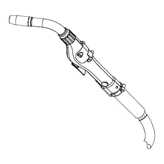
- Page 19 803 878-B Figure 7-3. Barrel Assembly Item Part Description Quantity Figure 7-3. Barrel Assembly ....215 687 Barrel Assy, Air/Water Cooled 60 Deg (Includes) ......
- Page 20 Item Part Description Quantity Figure 7-3. Barrel Assembly Consumables Flowchart Nozzles ♦176 238 ... Nozzle, Spot Flat ........... ♦176 240 .
- Page 21 803 877-B Figure 7-4. Power/Gas Connector Item Part Description Quantity Figure 7-4. Power/Gas Connector ... . . 602 172 Set Screw, 10-32 x 18 ..........
-
Page 22: Section 8 − Options And Accessories
SECTION 8 − OPTIONS AND ACCESSORIES Insulated Drive Roll Kits Used to prevent preheating of the wire which may soften it and clog the liner. This picking up of current at the drive rolls rather than at the contact tip is usually not a problem unless using too large of a contact tip or excessively oxidized aluminum wire. - Page 23 Effective January 1, 2006 (Equipment with a serial number preface of “LG” or newer) This limited warranty supersedes all previous Miller warranties and is exclusive with no other Warranty Questions? guarantees or warranties expressed or implied. LIMITED WARRANTY − Subject to the terms and conditions...
- Page 24 Contact the Delivering Carrier to: File a claim for loss or damage during shipment. For assistance in filing or settling claims, contact your distributor and/or equipment manufacturer’s Transportation Department. © PRINTED IN USA 2006 Miller Electric Mfg. Co. 2006−01...
Need help?
Do you have a question about the XR-A Python 25 Ft. and is the answer not in the manual?
Questions and answers