Table of Contents
Troubleshooting

Related Manuals for Miller Millermatic 252


Summary of Contents for Miller Millermatic 252
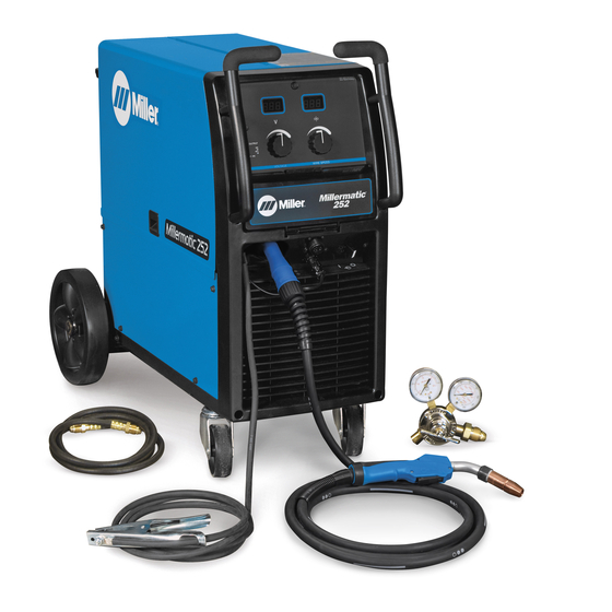
- Page 1 OM-230693S 2022-06 Processes MIG (GMAW) Welding Flux Cored (FCAW) Welding Description Arc Welding Power Source And Wire Feeder Millermatic ® OWNER’S MANUAL For product information, Owner’s Manual translations, and more, visit www.MillerWelds.com...
- Page 2 We know you don’t have time to do it any other way. That’s why when Niels Miller first started building arc welders in 1929, he made sure his products offered long-lasting value and superior quality.
-
Page 3: Table Of Contents
TABLE OF CONTENTS SECTION 1 – SAFETY PRECAUTIONS – READ BEFORE USING..............1 Symbol Usage . -
Page 5: Section 1 - Safety Precautions - Read Before Using
SECTION 1 – SAFETY PRECAUTIONS – READ BEFORE USING Protect yourself and others from injury—read, follow, and save these important safety precautions and operating instructions. 1-1. Symbol Usage DANGER! – Indicates a hazardous situation which, if not avoided, will result in death or serious injury. The possible hazards are shown in the adjoining symbols or explained in the text. - Page 6 HOT PARTS can burn. WELDING can cause fire or explosion. � Do not touch hot parts bare handed. � Allow cooling period before working on equipment. Welding on closed containers, such as tanks, drums, or pipes, can cause them to blow up. �...
-
Page 7: Additional Hazards For Installation, Operation, And Maintenance
� Never weld on a pressurized cylinder—explosion will result. CYLINDERS can explode if � Use only correct compressed gas cylinders, regulators, hoses, damaged. and fittings designed for the specific application; maintain them Compressed gas cylinders contain gas under high and associated parts in good condition. pressure. -
Page 8: California Proposition 65 Warnings
� To reduce possible interference, keep weld cables as short as ARC WELDING can cause possible, close together, and down low, such as on the floor. interference. � Locate welding operation 100 meters from any sensitive electronic equipment. � Electromagnetic energy can interfere with sensitive electronic equipment such as microprocessors, �... -
Page 9: Section 2 - Consignes De Sécurité - Lire Avant Utilisation
SECTION 2 – CONSIGNES DE SÉCURITÉ - LIRE AVANT UTILISATION Pour écarter les risques de blessure pour vous-même et pour autrui — lire, appliquer et ranger en lieu sûr ces consignes relatives aux précautions de sécurité et au mode opératoire. 2-1. - Page 10 � S’assurer que tous les panneaux et couvercles sont correctement LES ACCUMULATIONS DE GAZ en place. risquent de provoquer des blessures � Fixer le câble de retour de façon à obtenir un bon contact métal- ou même la mort. métal avec la pièce à souder ou la table de travail, le plus près possible de la soudure.
-
Page 11: Symboles De Dangers Supplémentaires En Relation Avec L'installation, Le Fonctionnement Et La Maintenance
� Brancher le câble de masse sur la pièce le plus près possible de � Les porteurs d’implants médicaux doivent consulter leur médecin la zone de soudage pour éviter le transport du courant sur une lon- et le fabricant du dispositif avant de s’approcher de la zone où se gue distance par des chemins inconnus éventuels en provoquant déroule du soudage à... - Page 12 � Affûter l'électrode au tungstène uniquement à la meuleuse dotée LIRE LES INSTRUCTIONS. de protecteurs. Cette manœuvre est à exécuter dans un endroit sûr lorsque l'on porte l'équipement homologué de protection du vi- � Lire et appliquer les instructions sur les étiquettes sage, des mains et du corps.
-
Page 13: Proposition Californienne 65 Avertissements
2-4. Proposition californienne 65 Avertissements AVERTISSEMENT – Ce produit peut vous exposer à des pro- Pour plus d’informations, consulter www.P65Warnings.ca.gov. duits chimiques tels que le plomb, reconnus par l’État de Californie comme cancérigènes et sources de malforma- tions ou d’autres troubles de la reproduction. 2-5. -
Page 14: Section 3 - Definitions
� Complete Parts List is available at www.MillerWelds.com SECTION 3 – DEFINITIONS 3-1. Symbols And Definitions Wire Feed Spool Do Not Stitch While Wire Feed Welding Press To Reset Volts www.MillerWelds.com Gas Metal Arc Duty Cycle Welding (GMAW) Gas Output FINITIONS Voltage Input Gas Input... -
Page 15: Section 4 - Specifications
Information About Default Weld Parameters And Settings NOTICE – Each welding application is unique. Although certain Miller Electric products are designed to determine and default to certain typical welding parameters and settings based upon specific and relatively limited application variables input by the end user, such default settings are for reference purposes only;... -
Page 16: Volt-Ampere Curves
� Complete Parts List is available at www.MillerWelds.com B. Temperature Specifications Operating Temperature Range* Storage/Transportation Temperature Range -4 to 104°F (-20 to 40°C) -22 to 122°F (-30 to 50°C) *Output is derated at temperatures above 104°F (40°C). 4-7. Volt-Ampere Curves 1 Normal Volt-Ampere Curves The volt-ampere curves show the normal minimum and maximum voltage and amper-... -
Page 17: Duty Cycle And Overheating
� Complete Parts List is available at www.MillerWelds.com 4-8. Duty Cycle And Overheating Duty Cycle is percentage of 10 minutes that unit can weld at rated load without overheating. If unit overheats, Thermistor (RT1) opens, output stops, and cooling fan runs. Wait fifteen minutes for unit to cool. -
Page 18: Section 5 - Installation
� Complete Parts List is available at www.MillerWelds.com SECTION 5 – INSTALLATION 5-1. Selecting A Location Do not move or operate unit where Movement it could tip. Special installation may be re- quired where gasoline or volatile liquids are present - see NEC Ar- ticle 511 or CEC Section 20. -
Page 19: Weld Output Terminals And Selecting Cable Sizes
� Complete Parts List is available at www.MillerWelds.com 5-2. Weld Output Terminals And Selecting Cable Sizes NOTICE – The Total Cable Length in Weld Circuit (see table below) is the combined length of both weld cables. For example, if the power source is 100 ft (30 m) from the workpiece, the total cable length in the weld circuit is 200 ft (2 cables x 100 ft). -
Page 20: Installing Work Cable And Clamp
� Complete Parts List is available at www.MillerWelds.com 5-4. Installing Work Cable And Clamp 1 Work Cable 2 Boot Route cable through front panel opening. Slide boot onto work cable. 3 Negative (-) Output Terminal Route work cable through hole in clamp han- dle. -
Page 21: Connecting Spoolmatic
� Complete Parts List is available at www.MillerWelds.com 5-5. Connecting Spoolmatic 15A Or 30A Gun ® 1 Gun Trigger Plug Insert plug into receptacle, and tighten threaded collar. 2 Weld Cable 3 Shielding Gas Hose Route weld cable through opening in front panel. -
Page 22: Connecting Xr Aluma-Pro, Xr Aluma-Pro Lite, Xr Edge, Xr-A Gun, Or Xr-A Python
� Complete Parts List is available at www.MillerWelds.com 5-6. Connecting XR Aluma-Pro, XR Aluma-Pro Lite, XR Edge, XR-A Gun, Or XR-A Python � XR Edge guns prior to serial no. LE079101 require an adapter cord (part no. 195498). 1 Gun End 2 Gun Liner 3 Wire Outlet Guide �... -
Page 23: Setting Gun Polarity For Wire Type
� Complete Parts List is available at www.MillerWelds.com 5-7. Setting Gun Polarity For Wire Type Polarity Changeover Label Information Always read and follow manufacturer’s rec- ommended polarity. 1 Wire Drive Assembly Lead 2 Work Clamp Lead 3 Negative Terminal 4 Positive Terminal Shown as shipped - Electrode Positive (DCEP): For solid steel, stainless steel, alu- minum, or flux core with gas wires (GMAW). -
Page 24: Installing Gas Supply
� Complete Parts List is available at www.MillerWelds.com 5-8. Installing Gas Supply Obtain gas cylinder and chain to running gear, wall, or other stationary support so cyl- inder cannot fall and break off valve. 1 Cap 2 Cylinder Valve Remove cap, stand to side of valve, and open valve slightly. -
Page 25: Installing Wire Spool And Adjusting Hub Tension
� Complete Parts List is available at www.MillerWelds.com 5-9. Installing Wire Spool And Adjusting Hub Tension Hand tighten knob clockwise. When a slight force is needed to turn spool, tension is set. To install either a 1 lb or 2 lb wire spool, fol- low the procedure as shown in the illustration. -
Page 26: Positioning Jumper Links (208/240 Volt Model)
� Complete Parts List is available at www.MillerWelds.com 5-10. Positioning Jumper Links (208/240 Volt Model) Check input voltage available at site. tools/ 208 VOLTS 240 VOLTS 1 Jumper Links Access Door Open door. 2 Jumper Link Label 284705-A allen_wrench allen_set flathead philips head wrench... -
Page 27: Positioning Jumper Links (230/460/575 Volt Model)
� Complete Parts List is available at www.MillerWelds.com 5-12. Positioning Jumper Links (230/460/575 Volt Model) Check input voltage available at site. tools/ 1 Jumper Links Access Door Open door. 2 Jumper Link Label 144916-E allen_wrench allen_set flathead philips head wrench crescent wre Check label −... -
Page 28: 5-14. Connecting Input Power
� Complete Parts List is available at www.MillerWelds.com 5-14. Connecting Input Power =GND/PE Earth Ground 240 VAC, 1 804912-A 2 Receptacle [NEMA Type 6-50R (Cus- Connect green or green/yellow grounding Installation must meet all National tomer Supplied)] conductor to disconnect device grounding and Local Codes —... -
Page 29: 5-15. Threading Welding Wire
� Complete Parts List is available at www.MillerWelds.com 5-15. Threading Welding Wire 6 in. (150 mm) philips head wrench crescent wrench tools/ nutdriver allen_wrench allen_set flathead philips head wrench crescent wrench chippinghammer Ref. 804913-B Step 1. Open pressure assembly. Step 6. Turn power on. Step 2. -
Page 30: 5-16. Weld Parameters
� Complete Parts List is available at www.MillerWelds.com 5-16. Weld Parameters OM-230693 Page 26... - Page 31 � Complete Parts List is available at www.MillerWelds.com 23.0/735 21.5/630 19.0/590 25.5/800 24.5/800 21.0/375 19.5/350 25.5/565 24.5/505 22.5/465 226650-E OM-230693 Page 27...
-
Page 32: Section 6 - Operation
� Complete Parts List is available at www.MillerWelds.com SECTION 6 – OPERATION 6-1. Controls 226647-B If the trigger on either gun is held for more power switch ON. The unit will power up with 1 Voltage Control than 3 seconds without striking an arc, the both the displays reading 888 , then the volt- unit will automatically shut off weld power age display will read run and the wire feed... -
Page 33: Voltmeter And Wire Feed Speed Meter Operation
� Complete Parts List is available at www.MillerWelds.com 6-2. Voltmeter And Wire Feed Speed Meter Operation When either a MIG gun or spool gun trigger The wire feed speed meter will display pre- 1 Voltmeter is pressed and a welding arc is established, set wire feed speed (IPM) for the appropri- 2 Wire Feed Speed Meter the voltmeter displays actual weld voltage. -
Page 34: Timers
� Complete Parts List is available at www.MillerWelds.com 6-4. Timers 226647-B Run-in speed (run) − The speed of the wire energized after the wire feeding has 1 Voltage Control prior to the welding arc being struck. The stopped. The range is from 0.01 to 0.25 2 Wire Speed Control range is from 25 to 150% of wire feed speed seconds. -
Page 35: Set Up Push Motor Torque (Sup) Or Reset (Res)
� Complete Parts List is available at www.MillerWelds.com 6-5. Set Up Push Motor Torque (SUP) Or Reset (rES) 226647-B 1 Voltage Control The following items can be adjusted by ro- � If Aluma-Pro push/pull gun has a listed tating the left knob counterclockwise (CCW): 2 Wire Speed Control SUP value, set the power source to 3 Voltmeter... -
Page 36: Section 7 - Maintenance And Troubleshooting
� Complete Parts List is available at www.MillerWelds.com plete Parts List is available at www.MillerWelds.com SECTION 7 – MAINTENANCE AND TROUBLESHOOTING 7-1. Routine Maintenance Disconnect power before maintaining. � Maintain more often during severe conditions. � = Check ◇ = Change �... -
Page 37: Aligning Drive Rolls And Wire Guide
� Complete Parts List is available at www.MillerWelds.com 7-4. Aligning Drive Rolls and Wire Guide Turn Off power. Correct View is from top of drive rolls looking down with pressure assembly open. 1 Drive Roll Securing Nut 2 Drive Roll 3 Wire Guide 4 Welding Wire 5 Drive Gear... -
Page 38: Troubleshooting Table
� Complete Parts List is available at www.MillerWelds.com 7-5. Troubleshooting Table Table 7–1. Troubleshooting Table Trouble Remedy No weld output; wire does not feed. Be sure line disconnect switch is On (see Section 5-14). Replace building line fuse or reset circuit breaker if open (see Section 5-14). Secure gun trigger connections (see welding gun Owner’s Manual). - Page 39 � Complete Parts List is available at www.MillerWelds.com Table 7–2. Help Codes � � All directions are in reference to the front of the unit. All circuitry referred to is located inside the unit. Volt- Wire Remedy meter Feed Dis- Speed play Meter...
-
Page 40: Section 8 - Electrical Diagram
SECTION 8 – ELECTRICAL DIAGRAM Figure 8-1. Circuit Diagram For 230/460/575 Volt Model OM-230693 Page 36... - Page 41 243035-D OM-230693 Page 37...
- Page 42 Figure 8-2. Circuit Diagram For 208/240 Volt Model OM-230693 Page 38...
- Page 43 286740-A OM-230693 Page 39...
-
Page 44: Section 9 - Gmaw Welding (Mig) Guidelines
SECTION 9 – GMAW WELDING (MIG) GUIDELINES 9-1. Typical GMAW (MIG) Process Connections 1 Wire Feeder/Welding Power Source 5 Gas Weld current can damage electronic parts in vehicles. Disconnect both 2 Gun 6 Shielding Gas battery cables before welding on a 3 Workpiece vehicle. - Page 45 Wire Size Amperage Range Recommended Wire Feed Speed Wire Feed Speed * 0.023 in. (0.58 mm) 30-90 A 3.5 in. (89 mm) per amp 3.5 x 62.5 A = 219 ipm (5.56 mpm) 0.030 in. (0.76 mm) 40-145 A 2 in. (51 mm) per amp 2 x 62.5 A = 125 ipm (3.19 mpm) 0.035 in.
- Page 46 9-4. Conditions That Affect Weld Bead Shape Gun Angles and Weld Bead Profiles � Weld bead shape depends on gun an- gle, direction of travel, electrode exten- sion (stickout), travel speed, thickness of base metal, wire feed speed (weld current), and voltage. 1 Push 2 Perpendicular 3 Drag...
- Page 47 9-5. Gun Movement During Welding � Normally, a single stringer bead is sat- isfactory for most narrow groove weld joints; however, for wide groove weld joints or bridging across gaps, a weave bead or multiple stringer beads works better. 1 Stringer Bead - Steady Movement Along Seam 2 Weave Bead - Side To Side Movement Along Seam...
- Page 48 9-8. Troubleshooting – Excessive Spatter Excessive Spatter - scattering of molten metal particles that cool to solid form near weld bead. Possible Causes Corrective Actions Wire feed speed too high. Select lower wire feed speed. Voltage too high. Select lower voltage range. Electrode extension (stickout) too long.
- Page 49 9-11. Troubleshooting – Lack Of Penetration Lack Of Penetration - shallow fusion between weld metal and base metal. Possible Causes Corrective Actions Improper joint preparation. Material too thick. Joint preparation and design must provide access to bottom of groove while maintaining proper welding wire extension and arc characteristics.
- Page 50 9-15. Troubleshooting – Distortion Distortion - contraction of weld metal during welding that forces base metal to move. Illustration: Base metal moves in the direction of the weld bead. Possible Causes Corrective Actions Excessive heat input. Use restraint (clamp) to hold base metal in position. Make tack welds along joint before starting welding operation.
-
Page 51: 9-17. Troubleshooting Guide For Semiautomatic Welding Equipment
9-17. Troubleshooting Guide For Semiautomatic Welding Equipment Problem Probable Cause Remedy Wire feed motor operates, but wire does not Too little pressure on wire feed rolls. Increase pressure setting on wire feed rolls. feed. Incorrect wire feed rolls. Check size stamped on wire feed rolls, re- place to match wire size and type if necessary. -
Page 52: Section 10 - Parts List
� Complete Parts List is available at www.MillerWelds.com SECTION 10 – PARTS LIST A. Drive Roll And Wire Guide Kits Base selection of drive rolls upon the following recommended usages: 6 V-Grooved rolls for hard wire. 7 U-Grooved rolls for soft and soft shelled cored wires. 8 U-Cogged rolls for extremely soft shelled wires (usually hard surfacing types). - Page 53 Notes...
- Page 54 Notes...
- Page 55 Effective January 1, 2022 (Equipment with a serial number preface of NC or newer) This limited warranty supersedes all previous Miller warranties and is exclusive with no other guarantees or war- ranties expressed or implied. � Field Options (NOTE: Field options are cov-...
- Page 56 Appleton, WI 54914 USA tact your distributor and/or equipment manu- facturer’s Transportation Department. International Headquarters–USA USA Phone: 920-735-4505 USA & Canada FAX: 920-735-4134 International FAX: 920-735-4125 For International Locations Visit www.MillerWelds.com ORIGINAL INSTRUCTIONS – PRINTED IN USA © Miller Electric Mfg. LLC 2022-06...
Need help?
Do you have a question about the Millermatic 252 and is the answer not in the manual?
Questions and answers