
Subscribe to Our Youtube Channel
Related Manuals for Siku RV 25 W Pro WiFi V2


Summary of Contents for Siku RV 25 W Pro WiFi V2
- Page 1 USER‘S MANUAL SIKU RV 25 W Pro WiFi V2 Single-room reversible energy regeneration ventilator siku.at...
- Page 2 SIKU RV 25 W Pro WiFi V2 unit of its products at any time in order to incorporate and all its modifications. Technical and maintenance the latest technological developments.
- Page 3 RV 25 W Pro WiFi V2 SIKU • Do not change the power cable length at your own discretion. • Do not lay the power cable of the unit • Do not bend the power cable. in close proximity to heating equipment.
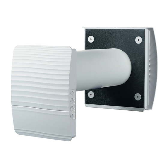
- Page 4 1 pc. AIR DUCT 1 pc. SOUND ABSORBING MAT 1 pc. ASSEMBLED CARTRIDGE 1 pc. OUTER VENTILATION HOOD 1 pc. CARDBOARD MOUNTING TEMPLATE 2 sets FASTENING KIT 1 set POLYSTYRENE WEDGES 1 pc. USER‘S MANUAL 1 pc. PACKING BOX siku.at...
- Page 5 The unit has Class II of protection against electric models may be slightly different from those ones shock and must not be grounded. described in this manual. MODEL SIKU RV 25 W PRO WIFI V2 SPEED 1 ~ 100~240 V ~ 50/69 Hz POWER SUPPLY VOLTAGE (V/HZ) 1,80...
- Page 6 Wärmerückgewinnung und Luftfiltration. Indoor unit front panel Außenabdeckung des Innenelementes Equipped with an automatic air damper that closes up the air duct at Mit einer automatischen Luftklappe versehen, the ventilator power off. die das Lüftungsrohr bei Abschalten der Lüftungsanlage schließt. siku.at siku.at...
- Page 7 RV 25 W Pro WiFi V2 SIKU VENTILATOR OPERATION MODES The ventilator has three operation modes: the ventilator runs either in extract or supply mode at a set speed. Ventilation: (available from a mobile device only): all the connected ventilators in the network go to the air Air supply: supply mode.
- Page 8 3 mm To cut the air duct, either make preliminary calculations of the required duct length or make sure to have access to the outer wall after fixation of the air duct. siku.at siku.at...
- Page 9 RV 25 W Pro WiFi V2 SIKU 3. Take the required mounting template and then fas- Then mark the fastening holes for installation of the ten it to the indoor wall using the adhesive tape. supplied dowels and drill the holes to a required The large opening in the template must be coaxial depth.
- Page 10 6. Insert the cartridge into the air duct and insert the plug cartridge to the controller. Re-install the front panel of the indoor unit rear part. siku.at siku.at...
- Page 11 RV 25 W Pro WiFi V2 SIKU CONNECTION TO POWER MAINS POWER OFF THE POWER SUPPLY PRIOR TO ANY OPERATIONS WITH THE UNIT. THE UNIT MUST BE CONNECTED TO POWER SUPPLY BY A QUALIFIED ELECTRICIAN. THE RATED ELECTRICAL PARAMETERS OF THE UNIT ARE GIVEN ON THE MANUFACTURER’S LABEL.
- Page 12 (see the figure below) • the mobile application SIKU RV WIFI installed on a smartphone or a tablet • The Smart home application. The ventilators must be connected to the Smart home application in compliance with user’s manual for this application.
- Page 13 RV 25 W Pro WiFi V2 SIKU VENTILATOR CONTROL WITH THE BUTTONS ON THE INDOOR UNIT On/Off The speed selection sequence is follows: low-medium-high. The speed of all the interconnected ventilators in the network is set with the Master unit.
- Page 14 The blinking Indicator identifies the Slave unit in the network and no connection with the Master unit. No glowing of the indicator identifies the Slave unit connected with the Master unit. Synchronous blinking of all the indicators on the ventilator casing indicates the activated Setup mode. siku.at siku.at...
- Page 15 RV 25 W Pro WiFi V2 SIKU VENTILATOR CONTROL WITH MOBILE APPLICATION To enable ventilator control with a mobile device, install the SIKU RV WIFI application. SIKU RV WIFI - APP STORE SIKU RV WIFI PLAY MARKET Your mobile device must have the operation system matching the following parameters: •...
- Page 16 Enter the SIKU RV WIFI app and create a new connection as follows: Enter the app menu. Select Connection - At home. If mobile device is connected to the Wi-Fi access point without router, select the default connection. In case of connection via router start searching for ventilators in the network.
- Page 17 RV 25 W Pro WiFi V2 SIKU DESCRIPTION OF MOBILE APPLICATION CONTROL BUTTONS ON/Standby. The Standby mode is determined by the DIP switch No. 2 position (see page 11). Selection of the pre-set speed: low, medium and high speed respectively.
- Page 18 The Party timer defines switch delay to the high speed after activation of the Party mode (4 hours by default). The turn-off delay timer for the Boost mode defines switch delay to the high speed after triggering of any sensor and reset of the sensor to the standard status. siku.at siku.at...
- Page 19 RV 25 W Pro WiFi V2 SIKU SENSOR SETUP To set up sensor operation via the mobile application, go to Menu–Settings–Sensors. Humidity sensor: actuation of the humidity sensor. When the indoor humidity exceeds the set point, the ventilator goes to the high speed. When the indoor humidity drops down below the set point, the turn-off delay timer for the Boost mode is activated.
- Page 20 In case of communication loss with the Master unit in the network. In this mode the ventilator responds longer than 20 seconds, the ventilator goes to the to signal from the sensors and goes to a respective Standby mode. operation mode. siku.at siku.at...
- Page 21 RV 25 W Pro WiFi V2 SIKU WI-FI PARAMETER SETUP Setup of the Wi-Fi parameters is only possible on Master units. To set up ventilator Wi-Fi parameters via the mobile app, go to Menu – Connection – WI-FI setup. Receive Press the button to display the current Wi-Fi settings.
- Page 22 Router Router with a Wi-Fi access point mit WLAN-Zugangspunkt Mobilgerät Mobilgerät Master Slave Nr.1 Slave Nr. N Extra wireless Zusätzlicher WLAN-Zugangspunkt access point Mobilgerät Mobilgerät Slave Nr. N+1 Slave Nr. N+N siku.at siku.at...
- Page 23 RV 25 W Pro WiFi V2 SIKU CONNECTING MASTER AND SLAVE VENTILATORS WHILE COMPLETING THE CONNECTION MAKE SURE THAT THE SLAVE UNITS ARE WITHIN COVERAGE OF THE BUILT-IN WI-FI IN THE MASTER UNIT. To connect a Master and a Slave unit, set the DIP switches on each ventilator to set it as a Master or the Slave unit (see page 12).
- Page 24 The battery is located on the control circuit board. Power off the ventilator to replace the battery, remove the front panel and the cover protecting the control circuit board. Remove the battery and install the new one. Battery type: CR1220. siku.at siku.at...
- Page 25 RV 25 W Pro WiFi V2 SIKU CLOUD SERVER CONNECTION The ventilators can be controlled using the mobile app via a cloud server connection. This functions enables control of a single or multiple ventilators connected according to Diagram 2 over any distance using the mobile app connected to the Internet.
- Page 26 Even regular technical maintenance may not completely prevent dirt accumulation on the regenerator and the fan. • Clean the regenerator regularly to ensure its high regeneration efficiency. • Clean the regenerator with a vacuum cleaner not less than once a year. siku.at siku.at...
- Page 27 RV 25 W Pro WiFi V2 SIKU FAILURES AND TROUBLESHOOTING FAILURE POSSIBLE REASONS TROUBLESHOOTING Make sure the power supply line is connected No power supply. correct, otherwise eliminate the connection error. The fan does not get started Turn the ventilator off. Troubleshoot the motor during turning on.
- Page 28 Failure to submit the user’s manual with the unit purchase date stamp. • Missing payment paperwork certifying the unit purchase. USER’S WARRANTY CLAIMS SHALL BE SUBJECT TO REVIEW ONLY UPON PRESENTATION OF THE UNIT, THE PAYMENT DOCUMENT AND THE USER’S MANUAL WITH THE PURCHASE DATE STAMP. siku.at siku.at...
- Page 29 This is to certify acceptance of the complete unit delivery with the user’s manual. The warranty terms are acknowledged and accepted. CUSTOMER’S SIGNATURE Seller’s Stamp INSTALLATION CERTIFICATE The SIKU RV __________________ unit is installed pursuant to the requirements stated in the present user‘s manual. COMPANY NAME ADDRESS PHONE NUMBER INSTALLATION TECHNICIAN’S...
- Page 30 Printing errors, mistakes and technical changes reserved. SIKU VertriebsgmbH | Bundesstraße 5 | 2102 Bisamberg | Austria | Tel.: +43 2262 61 521 | Fax: +43 2262 61 520 | www.siku.at | office@siku.at BDA_50522_SIKU_RV25W-V2_EN-01...
Need help?
Do you have a question about the RV 25 W Pro WiFi V2 and is the answer not in the manual?
Questions and answers