
Related Manuals for Siku RV 25 W Pro WiFi V2


Summary of Contents for Siku RV 25 W Pro WiFi V2
- Page 1 USER'S MANUAL SIKU RV 25 W Pro WiFi V2 Single-room reversible energy regeneration ventilator...
-
Page 2: Table Of Contents
This user’s manual is a main operating document intended for technical, maintenance, and operating staff. The manual contains information about purpose, technical details, operating principle, design, and installation of the SIKU RV 25 W Pro WiFi V2 unit and all its modifications. - Page 3 SIKU RV 25 W Pro WiFi V2 • Do not change the power cable length at your own discretion. Do not bend the power • Do not lay the power cable of the unit in cable. Avoid damaging the power cable. Do close proximity to heating equipment.
-
Page 4: Purpose
SIKU RV 25 W Pro WiFi V2 PURPOSE The ventilator is designed to ensure continuous mechanical air exchange in flats, cottages, hotels, cafés and other domestic and public premises. The ventilator is equipped with a regenerator that enables supply of fresh filtered air heated by means of extract air heat energy recovery. -
Page 5: Designation Key
SIKU RV 25 W Pro WiFi V2 TECHNISCHE DATEN The unit is designed for indoor application at outdoor air temperatures from -15 ˚C (5 °F) up to +40°C (104 °F) and relative indoor humidity up to 50 %. The unit has Class II of protection against electric shock and must not be grounded. -
Page 6: Unit Design And Operating Principle
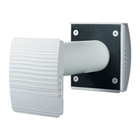
SIKU RV 25 W Pro WiFi V2 UNIT DESIGN AND OPERATING PRINCIPLE The ventilator consists of an indoor unit with a decorative front panel, a cartridge, an air duct with a sound absorbing mat and an outer ventilation hood. Cartridge is the basic functioning part of the ventilator. The cartridge consists of a fan, a regenerator and two filters that ensure rough air filtration and prevent ingress of dust and foreign objects into the regenerator and the fan. -
Page 7: Installation And Set-Up
SIKU RV 25 W Pro WiFi V2 FUNCTIONING OF AUTOMATIC AIR DAMPER The cover is The cover is Die Abdeckung Die Abdeckung ist The indoor unit has a front panel with automatic air damper. During the closed open ist geschlossen geö... - Page 8 SIKU RV 25 W Pro WiFi V2 3. Take the required mounting template and then fasten it to the indoor wall using the adhesive tape. The large opening in the template must be coaxial with the air duct. For aligning the template with respect to the horizon line it is recommended to use a builder’s level.
- Page 9 SIKU RV 25 W Pro WiFi V2 7. Insert the cartridge into the air duct and insert the plug cartridge to the controller. Re-install the front panel of the indoor unit rear part. www.siku.cc...
-
Page 10: Connection To Power Mains And Control
SIKU RV 25 W Pro WiFi V2 CONNECTION TO POWER MAINS AND CONTROL POWER OFF THE POWER SUPPLY PRIOR TO ANY OPERATIONS WITH THE UNIT. THE UNIT MUST BE CONNECTED TO POWER SUPPLY BY A QUALIFIED ELECTRICIAN. THE RATED ELECTRICAL PARAMETERS OF THE UNIT ARE GIVEN ON THE MANUFACTURER’S LABEL. - Page 11 (see the figure below) • the mobile application "SIKU RV WIFI" installed on a smartphone or a tablet • The Smart home application. The ventilators must be connected to the Smart home application in compliance with user’s manual for this application.
- Page 12 SIKU RV 25 W Pro WiFi V2 VENTILATOR CONTROL WITH THE BUTTONS ON THE INDOOR UNIT On/Off The speed selection sequence is follows: low-medium-high. The speed of all the interconnected ventilators in the network is set with the Master unit.
- Page 13 SIKU RV 25 W Pro WiFi V2 VENTILATOR CONTROL WITH MOBILE APPLICATION To enable ventilator control with a mobile device install the App SIKU RV WIFI application. SIKU RV WIFI - App Store SIKU RV WIFI Play Market Your mobile device must have the operation system matching the following parameters: •...
- Page 14 SIKU RV 25 W Pro WiFi V2 DESCRIPTION OF MOBILE APPLICATION CONTROL BUTTONS Standby ON/Standby. The mode is determined by the DIP switch No. 2 position (see page 11). Selection of the pre-set speed: low, medium and high speed respectively.
- Page 15 SIKU RV 25 W Pro WiFi V2 VENTILATOR PASSWORD CHANGE Menu-- To change the ventilator password in the mobile application go to Connection-At home. Settings 1. Select the connection type and press the button. 2. Enter and confirm the password.
- Page 16 SIKU RV 25 W Pro WiFi V2 DATE AND TIME SETUP Setting - Date and time. To set up the ventilator date and time, go to Current time: set the current time. Current date: set the current date. WEEKLY SCHEDULE SETUP Menu - Settings - Scheduler.
- Page 17 SIKU RV 25 W Pro WiFi V2 WIRELESS CONNECTION OF SEVERAL VENTILATORS The ventilator has two operation modes. Master unit (Master). The ventilator acts as a Master unit. The Slave Master units and the mobile devices are connected to the unit via the Wi-Fi connection.
- Page 18 SIKU RV 25 W Pro WiFi V2 VENTILATOR WIRELESS CONNECTION DIAGRAMS Wiring diagram 1 Slave Master Connection of up to 8 units or mobile devices to the Master Master-Anlage unit with its own wireless access point. mit WLAN-Zugangspunkt with a Wi-Fi access point Mobilgerät...
- Page 19 SIKU RV 25 W Pro WiFi V2 CONNECTING MASTER AND SLAVE VENTILATORS WHILE COMPLETING THE CONNECTION MAKE SURE THAT THE SLAVE UNITS ARE WITHIN COVERAGE OF THE BUILT-IN WI-FI IN THE MASTER UNIT To connect a Master and a Slave unit set the DIP switches on each ventilator to set it as a Master or the Slave unit (see page 11).
- Page 20 SIKU RV 25 W Pro WiFi V2 CLOUD SERVER CONNECTION The ventilators can be controlled using the mobile app via a cloud server connection. This functions enables control of a single or multiple ventilators connected according to Diagram 2 over any distance using the mobile app connected to the Internet.
-
Page 21: Technical Maintenance
SIKU RV 25 W Pro WiFi V2 TECHNICAL MAINTENANCE Maintenance of the ventilator means regular cleaning of the ventilator surfaces of dust and cleaning and replacement of the filters. To enable access to the main serviced units follow the procedure described below. Turn off the ventilator from power supply with the help of the automatic circuit breaker or the cut-out switch before. -
Page 22: Troubleshooting
SIKU RV 25 W Pro WiFi V2 FAILURES AND TROUBLESHOOTING Failure Possible reasons Troubleshooting Make sure the power supply line is connected No power supply correct, otherwise eliminate the connection error. The fan does not get started Turn the ventilator off. Troubleshoot the motor jam during turning on. -
Page 23: Manufacturer's Warranty
SIKU RV 25 W Pro WiFi V2 MANUFACTURER’S WARRANTY The product is in compliance with EU norms and standards on low voltage guidelines and electromagnetic compatibility. We hereby declare that the product complies with the provisions of Electromagnetic Council Directive 2014/30/EU, Low Voltage Directive 2014/35/ EU and CE-marking Directive 93/68/EEC. - Page 24 SIKU RV 25 W Pro WiFi V2 www.siku.cc...
- Page 25 SIKU RV 25 W Pro WiFi V2 www.siku.cc...
- Page 26 SIKU RV 25 W Pro WiFi V2 www.siku.cc...
-
Page 27: Certificate Of Acceptance
This is to certify acceptance of the complete unit delivery with the user’s manual. The warranty terms are acknowledged and accepted. Customer’s Signature Seller’s Stamp INSTALLATION CERTIFICATE The SIKU RV __________________ unit has been connected to power mains pursuant to the requirements stated in the present user’s manual. Seller Address Phone Number Installation Technician’s Full Name... - Page 28 SIKU VertriebsgmbH Tel.: +43 2262 61 521 Bundesstraße 5 Fax: +43 2262 61 520 2102 Bisamberg www.siku.cc BDA_50522_RV25W-V2_EN-01 Austria office@siku.cc...
Need help?
Do you have a question about the RV 25 W Pro WiFi V2 and is the answer not in the manual?
Questions and answers