
Related Manuals for Siku SPHERE WiFi 100


Summary of Contents for Siku SPHERE WiFi 100
- Page 1 USER‘S MANUAL SIKU SPHERE WiFi 100 SIKU SPHERE WiFi 160 Single-room reversible energy recovery ventilator siku.at...
- Page 2 The Company reserves the right to modify the techni- technical details, operating principle, design, and cal characteristics, design, or configuration of installation of the SIKU Sphere WiFi 100/160 unit and its products at any time in order to incorporate the all its modifications.
- Page 3 WiFi SIKU SPHERE WARNING! Similar to the use of any other household electrical appliances when operating this fan, the following basic rules must be followed: • Never touch the fan with wet or damp hands. • Never touch the fan when barefoot.
- Page 4 50 m³/h, Length of the ventilation pipe: 500 mm Series of reversible, WiFi-controlled SIKU Sphere WiFi 100: ventilation systems with a duct diameter of 100 mm and a nominal delivery rate of 30 m³/h, Length of the ventilation pipe: 500 mm siku.at...
- Page 5 Water: IP24. OVERALL DIMENSIONS OF THE INDOOR UNIT, MM ø 160 mm ø 103 mm TECHNICAL DATA MODELS SIKU SPHERE WIFI 100 SIKU SPHERE WIFI 160 VENTILATION LEVEL 100 - 240V ~ 50/60 Hz SUPPLY VOLTAGE (V/HZ) 1,80...
- Page 6 Decorative Front Panel Fulfils the decorative function. SIKU Sphere WiFi SIKU Sphere WiFi with the Frost outer hood (available as an accessory) siku.at siku.at...
- Page 7 OPEN, the horizontal one to the position CLOSED. damper can be manually moved to the CLOSED position SIKU Sphere WiFi using the handle to prevent drafts. The indoor unit of the ventilator is equipped with an automatic air damper.
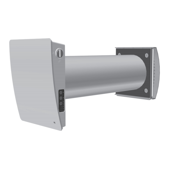
- Page 8 The figure below shows the minimum distance from the The corresponding values are given in the table. hole to the surrounding objects. The hole diameter VENTILATOR MODEL SIKU SPHERE WIFI 100 SIKU SPHERE WIFI 160 165 mm 270 mm CARTRIDGE LENGTH (L)
- Page 9 WiFi SIKU SPHERE 2. Insert the ventilation pipe into the wall. Use the from the wall by the distance A, which is required supplied assembly wedges to make assembly easier. On for the assembly of the external ventilation hood. the outer wall, the ventilation pipe must protrude The distance A is 0-10 mm.
- Page 10 Route the power cable as figured below and connect the ventilator to power mains in compliance with the external wiring diagram, see section Connection to power mains. Secure the power cable with the clamp. Circuit Board A3 Circuit Board A1 H1H2IN1IN2 siku.at siku.at...
- Page 11 WiFi SIKU SPHERE 9. After completion of the electrical connection reinstall the left cover in site. 10. Install the cartridge into the air duct as layer must be outside. Insert the sound absorbing figured below and connect the connector to the board.
- Page 12 NO contact of the external device is closed, the unit changes to the maximum speed.An analogue sensor with output voltage 0-10 V is also compatible with the unit. *The circuit breaker is not included in the delivery set. siku.at siku.at...
- Page 13 WiFi SIKU SPHERE SETTING THE VENTILATOR OPERATION MODE USING DIP SWITCHES Prior to operating the ventilator set it up using the DIP switch. It is located on the controller circuit board.To access the DIP switch, take off the front panel of the indoor unit and uplift the rubber plug that covers the switch.
- Page 14 • control buttons located on the side of the indoor unit (see the figure below) • „SIKU RV WIFI“ application from a mobile device (smartphone or tablet) VENTILATOR CONTROL WITH THE BUTTONS ON THE INDOOR UNIT Turning the ventilator on/off...
- Page 15 WiFi SIKU SPHERE Regeneration mode The rotation direction of both fans changes to opposite every 70 seconds. Heat recovery is performed in this mode. To enable reverse phase operation of the ventilators, change the position of the DIP switch No. 3.
- Page 16 VENTILATION UNIT OPERATION WITH THE MOBILE APPLICATION To enable operation of the unit with a mobile device, install the SIKU RV WIFI application to your mobile device. SIKU RV WIFI - APP STORE SIKU RV WIFI - PLAY MARKET •...
- Page 17 Warning! No communication with the device! Check the connection. Enter the SIKU RV WIFI app and create a new connection by following the steps below: Enter the app menu. Select Connection – At home. If the mobile device is connected to the Wi-Fi access point of the unit without a router, select the Default connection.
- Page 18 (30 minutes by default) the ventilation unit reverts to Power the previous mode. Press to deactivate this operation mode. Humidity indicator. It glows if the indoor humidity is above the set point. Indicator of external relay sensor. It glows if the external relay sensor is activated. siku.at siku.at...
- Page 19 WiFi SIKU SPHERE Indicator of the external analogue sensor 0-10 V. It indicates exceeding the setpoint on the external sensor. Alarm indicator It glows in emergency case and can be of two colours: lights up in case of emergency shutdown of the ventilator.
- Page 20 When the timer elapses, the ventilator reverts to the previous speed setting. DATE AND TIME SETUP To set the date and time of the ventilation system, open Menu - Settings – Date and time. Current time: set the current time. Current date: set the current date. siku.at siku.at...
- Page 21 WiFi SIKU SPHERE WEEKLY SCHEDULE SETUP To set up the weekly schedule in the mobile app, go to Menu – Settings – Schedule. The weekly schedule can be set by means of 4 time intervals available for each day of the week.
- Page 22 Master mode.In case of actuation of any sensors, external digital sensor, an external analogue sensor all the connected ventilators go to maximum speed. 0-10V and changes its operation mode respectively. siku.at siku.at...
- Page 23 WiFi SIKU SPHERE WI-FI PARAMETER SETUP Wi-Fi parameters are only set on Master units. To set up ventilator Wi-Fi parameters via the mobile app, go to Menu - Connection - Wi-Fi setup. Press the Receive button to display the current Wi-Fi settings. Select one of the Wi-Fi operation modes.
- Page 24 Router with its Router wireless access mit WLAN-Zugangspunkt point Mobilgerät Mobilgerät Mobile device Mobile device Master Slave Nr.1 Slave Nr.N Additional Wi-Fi Zusätzlicher WLAN-Zugangspunkt access point Mobile device Mobile device Mobilgerät Mobilgerät Slave Nr. N+1 Slave Nr. N+N siku.at siku.at...
- Page 25 WiFi SIKU SPHERE CONNECTING MASTER AND SLAVE VENTILATORS WHILE COMPLETING THE CONNECTION MAKE SURE THAT THE SLAVED VENTILATORS ARE WITHIN WI-FI COVERAGE OF THE MASTER VENTILATOR To connect a Master and a Slave unit, set the DIP switches on the units to the Master and Slave positions, respectively (see section Setting the ventilator operation mode using DIP switches).
- Page 26 Low battery power may cause disruptions in the battery and install a new one.The battery type is weekly schedule operation. Power off the unit before CR1220. Warning! The battery is low. The scheduler function will be incorrect. siku.at siku.at...
- Page 27 WiFi SIKU SPHERE CLOUD SERVER CONNECTION The ventilators can be controlled using the mobile app via a cloud server connection. This function enables control of a single or multiple ventilators connected according to Diagram 2 over any distance using the mobile app connected to the Internet.
- Page 28 Use a flat screwdriver Do not pull on the Ziehen Sie nicht an den Verwenden Sie dafür einen to disconnect the electric cable. Schlitzschraubenzieher. Leitungen! socket. 3. Remove the sound-insulation material from the duct, then remove the cartridge. siku.at siku.at...
- Page 29 WiFi SIKU SPHERE 4. Clean the filters as required (at least every 3 months). After 90 days of continuous operation, the lights up Filter change indicator (filter) on the ventilation system. The filter timer is reset by the mobile app or by pressing the button on the inner element of the master system for 5 seconds until the acoustic signal.
- Page 30 Failure of the device as a result of force majeure (fire, flood, earthquake, military action of any kind, blockages). • The seals are missing if the operating instructions provide for them. • Failure to present the operating instructions with the date of purchase. • Missing receipt with the purchase date, which confirms the purchase. siku.at siku.at...
- Page 31 This is to certify acceptance of the complete unit delivery with the user’s manual. The warranty terms are acknowledged and accepted. CUSTOMER’S SIGNATURE Seller’s Stamp INSTALLATION CERTIFICATE The SIKU Sphere WiFi __________ unit is installed pursuant to the requirements stated in the present user‘s manual. COMPANY NAME ADDRESS PHONE NUMBER INSTALLATIONTECHNICIAN’S FULL...
- Page 32 Printing errors, mistakes and technical changes reserved. SIKU VertriebsgmbH | Bundesstraße 5 | 2102 Bisamberg | Austria | Tel.: +43 2262 61 521 | Fax: +43 2262 61 520 | www.sikusphere.at | office@siku.at BDA_50675_50676_SIKU_Sphere_WiFi_EN-02...
Need help?
Do you have a question about the SPHERE WiFi 100 and is the answer not in the manual?
Questions and answers