
Related Manuals for Thor Broadcast F-GPS-Tx-WE


Summary of Contents for Thor Broadcast F-GPS-Tx-WE
- Page 1 User Manual One to Four GPS Signals over One to Four Fibers F-GPS-Tx-WE F-GPS-Rx-RM...
- Page 2 Disclaimer No part of this document may be reproduced in any form without the written permission of Thor Broadcast. The contents of this document are subject to revision without notice due to continued progress in methodology, design and manufacturing. Thor shall have no liability for any error or damage of any kind resulting from the use of this document.
-
Page 3: Table Of Contents
F-GPS-Tx-WE Table of Contents CHAPTER 1 - INTRODUCTION ......................... 1 ............................. 1 1.1 P RODUCT VERVIEW ..........................3 1.4 M ENU AND ESCRIPTION CHAPTER 2 – GPS TRANSMITTER INSTALLATION .................... 6 ......................... 6 2.1 R ECEIVING AND NSPECTING ............................... 6 2.2 P... -
Page 4: Chapter 1 - Introduction
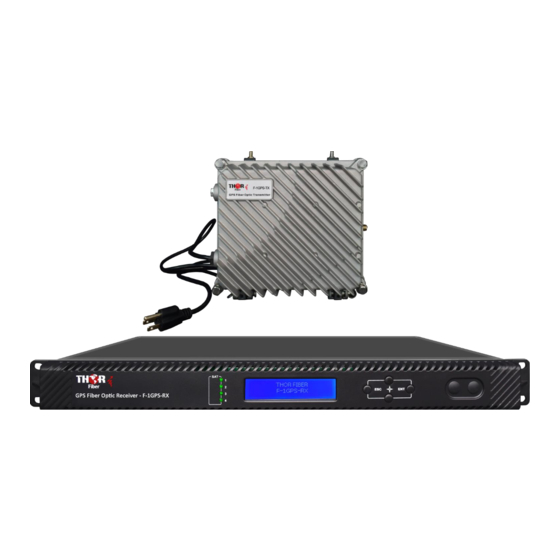
F-GPS-Tx-WE Chapter 1 - Introduction 1.1 Product Overview The Thor Fiber GPS over Fiber kit features a compact outdoor weatherproof enclosure Transmitter and a rack mount commercial grade Receiver. This satellite optical transmitter come equipped with a high linearity isolated DFB laser, direct modulated. It can transmit GPS signal (45~2400MHz) over glass, single mode fiber only. - Page 5 F-GPS-Tx-WE 1.3 Specifications Item Unit Indexes Remark Optical Characteristics Laser Type Isolated DFB 1510, 1530, 1550, Optical Wavelength 1570 or specified by Specified by the user the user Optical Output Power 1, 2, 3 Specified by the user Optical Return Loss...
-
Page 6: Menu And Description
F-GPS-Tx-WE Note 1: C/IM3 is defined as the ratio between the peak of carrier signal and triple beat (IM3) by using a two-tone test (1.0GHz and 1.1GHz). Note 2: The input level range is 47~67dBµV when AGC attenuation=0; the input level range is 48~68dBµV when AGC attenuation=1. - Page 7 F-GPS-Tx-WE 1.5 Menu Operation Trans Ente xx-xxxxxx 1. Disp Parameters 2.Set Parameters 3.Alarm Status Display parameters Description Trans xx-xxxxx Boot displayed xx-xxxxx is the device model Menu 1: Display parameters 1.Disp Parameters 2.Set Parameters Menu 2: Set parameters 3.Alarm Status...
- Page 8 F-GPS-Tx-WE Display parameters Description Optical Power Optical output power Laser bias current BIAS RF Level Laser input level +5V Read +5V monitor voltage Box temperature Box Temperature Serial number SofterWave Ver Software version number Setup Menu 1.5.2 2.Set Parameters Ente...
-
Page 9: Chapter 2 - Gps Transmitter Installation
F-GPS-Tx-WE Chapter 2 – GPS Transmitter Installation 2.1 Receiving and Inspecting As you unpack your unit, inspect the shipping container and equipment for damage. Save the shipping material for future use. If the container or the equipment is damaged, notify both the freight carrier and Thor Fiber. - Page 10 F-GPS-Tx-WE 2.3.3 Connecting the Optical Fiber Cables It has 1 to 4 output optical connectors (depending on custom order). DANGER: The fiber carries invisible laser radiation. AVOID DIRECT EXPOSURE TO BEAM. Never operate the unit with a broken fiber or with a fiber connector disconnected.
-
Page 11: Chapter 3 - Gps Receiver Parameters
F-GPS-Tx-WE Chapter 3 – GPS Receiver Parameters 3.1 Technical Specifications Item Unit Indexes Remark Optical Characteristics Operating Wavelength 1260~1620 ≥0.9 Responsivity ≥50 Optical Return Loss Optical Connector Type SC/APC Specified by the user Optical Receiving Power -15 ~0 RF Characteristics... -
Page 12: Panel Interface
F-GPS-Tx-WE 3.2 Panel Interface Module 1 indicator Module 2 indicator Module 3 indicator Module 4 indicator Down Enter 3.3 Menu Operation 3.3.1. Main Menu RECV Ente xx-xxxxxx 1. Disp Parameters 2.Set Parameters 3.Alarm Status Display parameters Description RECV xx-xxxxx Boot displayed xx-xxxxx is the device model 1.Disp Parameters... - Page 13 F-GPS-Tx-WE 3.3.2 Display Menu 1.Disp Parameters Ente Optical Power: -xx.xdBm RF Level: -xx.xdBm +5V Read: x.xV Box Temperature: xx.x℃ S/N: xxxx.xx.xx Address: xxx.xxx.xxx.xxx Mask: xxx.xxx.xxx.xxx Net GateWay: xxx.xxx.xxx.xxx MAC: XXXXXXXXXXXX Trap Addr1: xxx.xxx.xxx.xxx Trap Addr2: xxx.xxx.xxx.xxx SofterWave Ver: Vx.x Display parameters...
- Page 14 F-GPS-Tx-WE 3.3.3. Setup Menu 2.Set Parameters Ente Set Channel Number xxx.xxx.xxx.xxx Set Local IP Address xxx.xxx.xxx.xxx Set SubNet Mask xxx.xxx.xxx.xxx Set GateWay xxx.xxx.xxx.xxx Set Trap Addr1 xxx.xxx.xxx.xxx Set Trap Addr2 Set Buzzer Switch Restore Factory Display parameters Description Remark Set Channel Number...
-
Page 15: Chapter 4 - Installation
F-GPS-Tx-WE Chapter 4 – Installation 4.1 Receiving and Inspecting As you unpack your unit, inspect the shipping container and equipment for damage. Save the shipping material for future use. If the container or the equipment is damaged, notify both the freight carrier and us. -
Page 16: Mounting The Equipment
F-GPS-Tx-WE 4.3 Mounting the equipment 4.3.1 Mount the equipment in the cabinet To mount the equipment in a standard 19-inch equipment cabinet/Rack: 1. Place the unit in the cabinet/Rack. 2. Use four mounting screws to attach the mounting ears on the front panel to the cabinet. -
Page 17: Chapter 5 - Packing List
F-GPS-Tx-WE 4.3.4 Connecting the Ethernet Cable You can connect the equipment to your TCP/IP network in order to monitor and control the optical receiver remotely. After you complete the installation procedures described in this chapter, you can use a network management system (NMS) to monitor and control the equipment.
Need help?
Do you have a question about the F-GPS-Tx-WE and is the answer not in the manual?
Questions and answers