Table of Contents
Advertisement
Quick Links
EN
2 0 . 1 0 - 5 2 9 9 6 7 6 _ 0 1
T r a n s l a t i o n f r o m o r i g i n a l
C K G
u n i v e r s a l 2 6 0 F S - u n i v e r s a l 3 6 0 F S - m o n o s p l i t 5 0 0 F S
I n s t a l l a t i o n m a n u a l
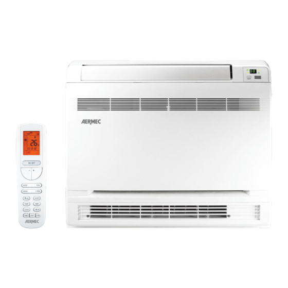
CONSOLE
C o o l i n g c a p a c i t y f r o m 2 , 7 k W t o 6 , 6 k W
H e a t i n g c a p a c i t y f r o m 2 , 9 k W t o 6 , 8 k W
w w w . a e r m e c . c o m
Advertisement
Table of Contents

Related Manuals for AERMEC CKG universal 260FS CONSOLE


Summary of Contents for AERMEC CKG universal 260FS CONSOLE
- Page 1 2 0 . 1 0 - 5 2 9 9 6 7 6 _ 0 1 T r a n s l a t i o n f r o m o r i g i n a l C K G u n i v e r s a l 2 6 0 F S - u n i v e r s a l 3 6 0 F S - m o n o s p l i t 5 0 0 F S I n s t a l l a t i o n m a n u a l CONSOLE...
- Page 2 Dear customer, Thank you for choosing an AERMEC product. It is the fruit of many years of experience and special design studies and has been made of the highest grade materials and with cutting edge technology. In addition, all our products bear the CE mark indicating that they meet the requirements of the European Machine Directive regarding safety.
-
Page 3: Table Of Contents
INDEX SAFETY STANDARDS - R32 GAS ......................................4 WARNINGS ..............................................6 UNIT TYPE ..............................................9 FEATURES ..............................................9 NOTES ON OPERATION ........................................9 ACCESSORIES ............................................11 TECHNICAL DATA ..........................................11 INDOOR UNIT ............................................12 GENERAL DATA .............................................12 NOTES FOR INSTALLATION OF UNIT ....................................13 SIZES AND WEIGHTS ..........................................15 TECHNICAL DIMENSIONS ........................................16 TECHNICAL DIMENSIONS - DIMES ....................................16 MINIMUM TECHNICAL CLEARANCES ..................................17 INSTALLING THE INDOOR UNIT .....................................19... -
Page 4: Safety Standards - R32 Gas
SAFETY STANDARDS - R32 GAS 1. GAS R32 - WARNINGS WARNINGS FOR MAINTENANCE OR REPAIR THESE PROCEDURES MAY ONLY BE FOLLOWED GAS R32 GENERAL WARNINGS BY SPECIALISED TECHNICIANS OR QUALIFIED WARNING PERSONNEL. Please read this manual carefully before Please follow the steps below: using the unit. - Page 5 WARNING: Do not use means to accelerate the defrosting process or to clean, other than those recommended by the manufacture. Should repair be necessary, contact your nearest authorized Service Centre. Any repairs carried out by unqualified personnel may be dangerous. The appliance shall be stored in a room without continuously operating ignition sources.
-
Page 6: Warnings
1. WARNINGS WARNINGS poisonous, corrosive or hazardous substances. Do not use naked flames near the units. Risk of fire or explosion. Install the unit in a location Split-system air conditioners are designed solely for the with minimal levels of dust, fumes, humidity and purpose of air conditioning indoor rooms of a certain corrosive agents in the air. - Page 7 • This air conditioner must be installed according to • Do not pull or deform the supply cable. If the cable national plant engineering regulations. Particular is pulled or used inappropriately, the unit could be damaged and there is a risk of electric shock. attention must be paid to safety guidelines and •...
- Page 8 • When operating in Cooling mode, the temperature WARNINGS - INDOOR UNIT selected must not be more than 5°C below the outdoor temperature, for optimum comfort and energy saving. • Install the indoor unit and the remote control at least •...
-
Page 9: Unit Type
UNIT TYPE NOTES ON OPERATION 1. NOTES ON OPERATION Indoor units of the type "CONSOLE" in split-system air condi- tioners are designed to be installed on walls indoors. DEFROSTING THE OUTDOOR UNIT The air filter is easily accessible to enable regular cleaning. The "CONSOLE"... - Page 10 AIR PURIFIER (COLD PLASMA) Capable of reducing pollutants breaking down their mole- cules using electric discharges, causing the splitting of the water molecules in the air into positive and negative ions. These ions neutralise the molecules of the gaseous pollut- ants obtaining products that are normally present in clean air.
-
Page 11: Accessories
ACCESSORIES 260FS 360FS 500FS WRCA • • • CC2 * • • • • compatible – not compatible * The accessory CC2 version 01 is compatible with the indoor units of the CKG_FS series, from version TECHNICAL DATA Indoor unit CKG260FS CKG360FS CKG500FS... -
Page 12: Indoor Unit
INDOOR UNIT Indoor unit CKG260FS CKG360FS CKG500FS Input power Type of fan Type Inverter centrifugal Inverter centrifugal Inverter centrifugal Air flow rate Turbo m³/h Maximum m³/h Average m³/h Minimum m³/h Sound power Turbo db(A) 50,0 54,0 57,0 Maximum dB(A) 48,0 50,0 55,0 Average... -
Page 13: Notes For Installation Of Unit
INSTALLATION NOTES FOR INSTALLATION OF UNIT measures to avoid heat dispersion and the consequent formation of condensate. Incorrect installation of the pipes can result in water leaks, wetting furniture and other items in the room. WARNINGS CONCERNING INSTALLATION NOISE • The unit and its accessories must only be installed and wired by professionals with the necessary •... - Page 14 WIRING • The unit and its accessories must only be installed and wired by professionals with the necessary technical qualifications in installation, conversion, extension and maintenance of the systems and who EARTHING: are trained to perform operational and safety checks Check the earth cable is connected to the on these systems.
-
Page 15: Sizes And Weights
SIZES AND WEIGHTS MLG_FS CKG_FS Without Net Weight packaging (mm) (mm) (mm) (kg) CKG260FS 15,5 CKG360FS 15,5 CKG500FS 15,5 With packag- Gross (mm) (mm) (mm) weight (kg) CKG260FS 18,5 CKG360FS 18,5 CKG500FS 18,5 Carton Box Example... -
Page 16: Technical Dimensions
TECHNICAL DIMENSIONS CKG_FS (mm) (mm) (mm) CKG260FS CKG360FS CKG500FS TECHNICAL DIMENSIONS - DIMES CKG_FS (mm) (mm) (mm) CKG260FS CKG360FS CKG500FS... -
Page 17: Minimum Technical Clearances
1. MINIMUM CLEARANCES FOR INDOOR UNIT MINIMUM TECHNICAL CLEARANCES • Install the unit further than 1m away from other electrical appliances such as TVs, radios, audio equipment, etc. CHOOSING THE INSTALLATION AREA FOR THE • Do not install the unit in a location where it could be INDOOR UNIT affected by inflammable gas leaks. - Page 18 Floor installation Flush installation (with support) Semi-flush installation Recess installation...
-
Page 19: Installing The Indoor Unit
INSTALLING THE INDOOR UNIT (1) Open the front panel The installation of the indoor unit requires observance of the following indications: Open the front panel to access the fixing screws of the front grille; Remove the 4 fixing screws of the front grille; Remove the front grille;... - Page 20 1. Choose the place on the wall where the unit will be 6. Service hole (if the installation requires), diameter 55- installed. 65mm (for electric line providing supply and commu- 2. Calculate the locations where the wall must be nication with the outdoor unit, condensate discharge drilled using the cardboard template provided as a and copper pipes).
- Page 21 Position to create the service holes: Wall LH connections RH connections Wall LH connections RH connections RH/LH connections floor floor Side pre-sheared (on the RH and LH sides)
- Page 22 AIR SUPPLY SELECTION This type of unit intakes the air on the side and delivers it into the room through two different deliveries, an upper and a lower one; however it is possible to exclude the lower delivery by means of the following procedure: Open the front panel;...
-
Page 23: Fitting The Refrigerant Lines
FITTING THE REFRIGERANT LINES To prepare the copper pipes, proceed as follows: External Pipe Tightening Pipe thickness 1. Measure the inner and outer pipe precisely. Diameter Torque 2. Use a pipe which is slightly longer than the inch (mm) measurement taken. 1/4˝... - Page 24 Fig. A Fig. B Fig. C Fig. D Fig. E Fig. F...
-
Page 25: Condensate Discharge
1. CONDENSATE DRAIN CONDENSATE DISCHARGE • The outlet direction of the condensate discharge hose can be chosen according to the plant requirements of the indoor unit. • The diameter of the condensate discharge hose must be the same as - or greater than - the diameter of the connection pipe. -
Page 26: Electrical Wirings
1. ELECTRICAL WIRINGS ELECTRICAL WIRINGS fans. • Do not modify the circuits inside the air conditioner. The manufacturer cannot be held responsible for • Before carrying out any work, switch off the power any damage or malfunction due to incorrect line supply to the air conditioner. - Page 27 NOTE: • Circuit Breaker and Power Cord Specifications are selected according to the Rated Power Input (Rated Current Input) of the Unit. Rated Power Input (Rated Current Input) is “Maximum” Power Input (“Maximum” Current Input) of the Unit according to EN 60335-1 and EN 60335-2-40.
-
Page 28: Wiring Diagrams
WIRING DIAGRAMS CKG260FS WARNING SWITCH MOTOR ROOM TEMP. TUBE TEMP. RECEIVER AND Please don't touch any electronic SELECT component or terminal when the SENSOR SENSOR DISPLAY BOARD machine is running,stopping or has been powered off for less DISPLAY than 3 minutes to prevent electric shock ! MOTOR FRAME DC-MOTOR... - Page 29 CKG360FS - CKG500FS WARNING SWITCH ROOM TEMP. TUBE TEMP. RECEIVER AND MOTOR Please don't touch any electronic SELECT component or terminal when the SENSOR SENSOR DISPLAY BOARD machine is running,stopping or has been powered off for less DISPLAY than 3 minutes to prevent electric shock ! MAGNETIC RING...
-
Page 30: Checks To Be Carried Out After Installation
1. ROUTINE CHECKS FOLLOWING CHECKS TO BE CARRIED OUT AFTER INSTALLATION INSTALLATION ITEMS TO CHECK POSSIBLE ANOMALY NOTES Is the unit firmly fixed? The unit could fall, vibrate or make noise. Was the unit checked for refrigerant Insufficient output. leaks? Is the thermal insulation sufficient? It could cause condensate and dripping water. -
Page 31: Maintenance
MAINTENANCE GENERAL NOTES CHECK BEFORE STARTING • Disconnect the power supply before cleaning the • Check to make sure that the inlet and outlet are not unit. obstructed by objects on both units, external and • Disconnect the power supply when the air internal. -
Page 32: Troubleshooting
1. TROUBLESHOOTING TROUBLESHOOTING Anomaly Possible causes The unit cannot be started. • The power supply is not connected. • Check if the power supply cable is damaged. • Check for anomalies on the power supply. • Voltage is too low. The units stops after operating a while. -
Page 33: Error Code List
ERROR CODE LIST If malfunctioning occurs during system functioning, the units show the relative alarm code which easily permits to the After-Sales Service Area to identify the cause of errors; such alarm code will appear both on indoor unit (through two-digit display and possibly through the flashing symbols cooling and heating) and on outdoor unit (by flashing LEDs on the electronic board);... - Page 34 Indoor unit Alarm description codes System under protection against compressor overheating Current control module protection No signal return from the outdoor unit fan Compressor out of synch PFC protection Fan 1 malfunction (blocked fan or not connected) power protection Error detection indoor/outdoor unit (wrong matching) Compressor start-up failed Anti-freeze protection Undefined outdoor unit error...
- Page 36 TÉLÉCHARGER LA DERNIÈRE VERSION: TÉLÉCHARGER LA DERNIÈRE VERSION: http://www.aermec.com/qrcode.asp?q=14746 http://www.aermec.com/qrcode.asp?q=14747 http://www.aermec.com/qrcode.asp?q=14748 A E R M E C S . p . A . V i a R o m a , 9 9 6 - 3 7 0 4 0 B e v i l a c q u a ( V R ) - I t a l y T e l .
Need help?
Do you have a question about the CKG universal 260FS CONSOLE and is the answer not in the manual?
Questions and answers