Table of Contents
Advertisement
Quick Links
UM3301-M
User manual
MB1803B-01
Introduction
MB1801B-01
is wireless and ultra-low-power board embedding a powerful and ultra‑low‑power radio compliant with the
®
Bluetooth
Low Energy SIG specification v5.3, IEEE 802.15.4-2015 PHY and MAC, supporting Thread, Chip and Zigbee®.
Figure 1 NUCLEO-WBA55CG global view
UM3301 - Rev 3
page 1/26
Advertisement
Table of Contents

Related Manuals for ST MB1801B-01


Summary of Contents for ST MB1801B-01
-
Page 1: Figure 1 Nucleo-Wba55Cg Global View
UM3301-M User manual MB1803B-01 Introduction MB1801B-01 is wireless and ultra-low-power board embedding a powerful and ultra‑low‑power radio compliant with the ® Bluetooth Low Energy SIG specification v5.3, IEEE 802.15.4-2015 PHY and MAC, supporting Thread, Chip and Zigbee®. Figure 1 NUCLEO-WBA55CG global view... -
Page 2: Features
UM3301-M 1. Features ‑M33 core, featuring • Ultra-low-power wireless STM32WBA55CG microcontroller based on the Arm ® Cortex ® 1 Mbyte of flash memory and 128 Kbytes of SRAM in a UFQFPN48 package • MCU RF board (MB1803): – 2.4 GHz RF transceiver supporting Bluetooth ®... -
Page 3: Ordering Information
UM3301-M 2. Ordering information To order the NUCLEO-WBA55CG board, refer to Table 1. Additional information is available from the datasheet and reference manual of the target microcontroller. Table 1. List of available products Order code Board reference Target STM32 MB1803B-01 STM32WBA55CG MB1803 2.1 Codification... -
Page 4: Development Environment
STM32 flash memory for easy demonstration of the device peripherals in standalone mode. The latest versions of the demonstration source code and associated documentation can be downloaded from www.st.com. UM3301 - Rev 3 page 4/26... -
Page 5: Conventions
UM3301-M 4. Conventions Table 3 provides the conventions used for the ON and OFF settings in the present document. Table 3. ON/OFF convention Convention Definition Jumper JPx ON Jumper fitted Jumper JPx OFF Jumper not fitted Jumper JPx [1-2] Jumper fitted between Pin 1 and Pin 2 Solder bridge SBx ON SBx connections closed by 0 Ω... -
Page 6: Safety Recommendations
UM3301-M 5. Safety recommendations 5.1 Targeted audience This product targets users with at least basic electronics or embedded software development knowledge like engineer, technician, or student. This board is not a toy and is not suited for use by children. 5.2 Handling the board This product contains a bare printed circuit board and as with all products of this type, the user must be careful about the following points:... -
Page 7: Hardware Layout And Configuration
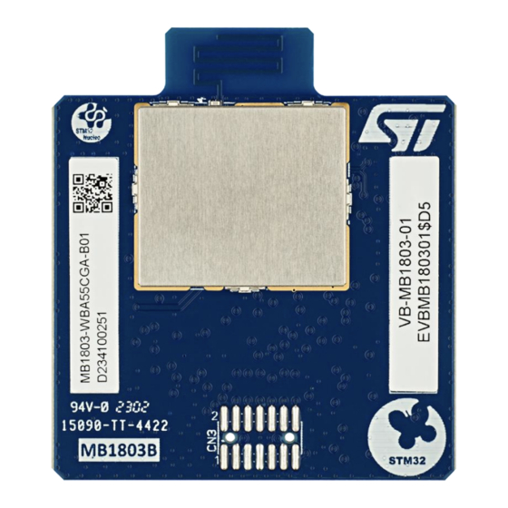
Figure 2 illustrates the connection between STM32WBA55CG ® and peripherals (ARDUINO Uno V3 connectors, ST morpho connector, and embedded ST-LINK). Figure 3 helps users locate these features on the MB1803B-01 board. The mechanical dimensions of the NUCLEO-WBA55CG product are shown in... - Page 8 UM3301-M Figure 3 NUCLEO-WBA55CG PCB details of the MCU RF board (MB1803) Figure 4 NUCLEO-WBA55CG (MB1803B) mechanical dimensions (in millimeters) UM3301 - Rev 3 page 8/26...
-
Page 9: Power Supply
UM3301-M 6.1 Power supply The STM32WBA55CG can be supplied by an external source (between 1.8 and 3.3 V). this figure also shows the default state of the jumpers and the solder bridges. Figure 5 MB1803B-01 power tree UM3301 - Rev 3 page 9/26... -
Page 10: Debug
UM3301-M 6.2 Debug By default, the debug connector is not assembly on the MB1803B-01. If necessary, the connector should be soldered. By this way, that allows to select the type of connector STDC14 or MIPI10. The foot print is compatible with the both connectors. Figure 6 CN3 assembly for debug connector It is also necessary to add some components on the bottom side of the MB1803. -
Page 11: Clock Sources
UM3301-M 6.3 Clock sources 7.2.1 HSE clock references The accuracy of the high‑speed clock (HSE) of the MCU RF board is committed to a 32 MHz crystal oscillator. The HSE oscillator is trimmed during board manufacturing. 7.2.2 LSE clock references The accuracy of the low‑speed clock (LSE) of the MCU RF board is committed to a 32.768 kHz crystal oscillator. -
Page 12: Rf I/O Stage
Due to FCC/ISED constraints, the antenna cannot be removable. So, the board is proposed by default with a PCB antenna. This antenna is described on AN5129 available on the ST web site. Between the STM32WBA55 and the antenna, there is a passive network. This network has got two functions: makes a low pass filter and matches the impedance of the PCB antenna. -
Page 13: Mcu Rf Board Interface And Pinout
6.6 MCU RF board interface and pinout 7.11.1 Description The ST-MCU RF board connectors (CN1 and CN2) are accessible on the top side of the board. They are used to plug the MCU RF board into the mezzanine board. 7.11.2 Board pinout... - Page 14 UM3301-M Table 11. Pinout of the MCU RF board connectors STM32WBA55CG STM32WBA55CG STM32WBA55CG STM32WBA55CG number pin name number pin name number pin name number pin name VDD1 BOOT0 NRST PB3/SWO PA13 PA14 PA15 VDD3 VDDA PA12 /PA15 /JTDI PB15/PA11 PB9/PC13 PA12 VDD4 PA11...
-
Page 15: Mipi10/Stdc14 Connector Pinout
UM3301-M 6.7 MIPI10/STDC14 connector pinout 7.12.1 Description On the MCU RF Board, there is a footprint for direct debug. This footprint is compatible with MIPI10 and STDC14 connectors. STDC14 is an extension of the MIPI10 connector. By default, on this footprint (CN3), the connector is not assembly. If some features not available on the STlinkV3EC embedded on MB1801, it’s possible to solder a MIPI10 or STDC14 connector. - Page 16 UM3301-M Table 12. Pinout of the MIPI10/STDC14 connector (CN3 of the MCU RF board) STDC14 pin # MIPI10 pin # Pin description Type Reserved Reserved T_VCC T_JTMS/T_SWDIO T_JCLK/T_SWCLK T_JTDO/T_SWO T_JCLK T_JTDI/NC GNDDetect T_NRST T_VCP_RX T_VCP_TX UM3301 - Rev 3 page 16/26...
-
Page 17: Mb1801B-01 Product Information
B01. The second line shows the board serial number used for traceability. Parts marked as “ES” or “E” are not yet qualified and therefore not approved for use in production. ST is not responsible for any consequences resulting from such use. In no event will ST be liable for the customer using any of these engineering samples in production. -
Page 18: Mb1801B-01 Product History
UM3301-M 8. MB1801B-01 product history Table 13. Product history Order Product code identification Product details Product change description Product limitations MCU: STM32WBA55CGU6 silicon revision "Z" MCU errata sheet: STM32WBA55xx device errata MB1801B-01 Initial revision No limitation (ES0592) Boards: MB1803-WBA55CG-B01 8.1 Boards revision history Table 14. -
Page 19: Federal Communications Commission (Fcc) And Ised Canada
UM3301-M 9. Federal Communications Commission (FCC) and ISED Canada 9.1 FCC Compliance Statement Changes or modifications not expressly approved by STMicroelectronics could void the user’s authority to operate the equipment. This device complies with part 15 of the FCC Rules. Operation is subject to the following two conditions: (1) This device may not cause harmful interference, and (2) this device must accept any interference received, including interference that may cause undesired operation. -
Page 20: Ised Compliance Statement
UM3301-M 9.2 ISED Compliance Statement IC: 8976A- MB180300 Product Marketing Name: MB1803B HVIN: MB1803B-01 This device contains licence-exempt transmitter(s)/receivers(s) that comply with Innovation, Science and Economic Development Canda’s licence-exempt RSS(s). Operation is subject to the following two conditions: This device may not cause interference. This device must accept any interference, including interference that may cause undesired operation of the device. -
Page 21: Isde - Canada, Appareils Radio Exempts De Licence
UM3301-M 9.3 ISDE – Canada, Appareils radio exempts de licence IC: 8976A-MB180300 Nom de marque du produit: MB1803B NIVM: MB1803B-01 L’émetteur/récepteur exempt de licence contenu dans le présent appareil est conforme aux CNR d’Innovation, Sciences et Développement économique Canada applicables aux appareils radio exempts de licence. L’exploitation est autorisée aux deux conditions suivantes : L’appareil ne doit pas produire de brouillage. -
Page 22: Red Compliance Statement
Hereby, the manufacturer STMicroelectronics, declares that the radio equipment type “MB1803B-01” is in compliance with The UK Radio Equipment Regulations 2017 (UK S.I. 2017 No. 1206). The full text of the UK declaration of conformity is available at the following internet address: www.st.com UM3301 - Rev 3 page 22/26... -
Page 23: Revision History
UM3301-M 12. Revision history Table 15. Document revision history Date Revision Changes 13-Dec-2023 Initial release. 22-Feb-2024 Updated FCC information 29-Feb-2024 Updated ISED information UM3301 - Rev 3 page 23/26... -
Page 24: Table Of Contents
Board pinout ........................13 MIPI10/STDC14 connector pinout ..................15 7.12.1 Description ..........................15 7.12.2 MIPI10/STDC14 pinout ......................15 MB1801B-01 product information .................. 17 Product marking ......................... 17 MB1801B-01 product history ..................18 Boards revision history ....................... 18 Federal Communications Commission (FCC) and ISED Canada ........ 19 FCC Compliance Statement .................... -
Page 25: List Of Figures
UM3301-M RED Compliance Statement ................. 22 11. UKCA Compliance Statement ..................22 Revision history ....................23 List of tables ................... Error! Bookmark not defined. List of figures ........................... 25 List of figures Figure 1 NUCLEO-WBA55CG global view ..........................1 Figure 2 Hardware block diagram ............................7 Figure 7 Components to add for STLink-V3PWR ........................ - Page 26 STMicroelectronics NV and its subsidiaries (“ST”) reserve the right to make changes, corrections, enhancements, modifications, and improvements to ST products and/or to this document at any time without notice. Purchasers should obtain the latest relevant information on ST products before placing orders. ST products are sold pursuant to ST’s terms and conditions of sale in place at the time of order acknowledgment.
Need help?
Do you have a question about the MB1801B-01 and is the answer not in the manual?
Questions and answers