Table of Contents
Advertisement
Quick Links
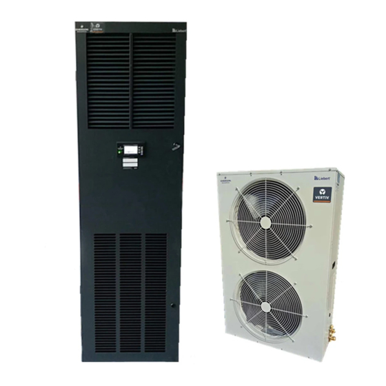
Liebert PEX Heat Rejection
Condenser User Manual
Version
Revision date
BOM
Vertiv provides customers with technical support. Users may contact the nearest Vertiv local sales office
or service center.
Copyright © 2008 by Vertiv Co., Ltd.
All rights reserved. The contents in this document are subject to change without notice.
Vertiv Co., Ltd.
Address: No.1 Kefa Rd., Science & Industry Park, Nanshan District 518057, Shenzhen China
Homepage: www. Vertiv.com.
E-mail:
support@Vertiv.com
V1.1
Mar. 09, 2022
31012632
Advertisement
Table of Contents
Troubleshooting


Need help?
Do you have a question about the LSF24 and is the answer not in the manual?
Questions and answers