Table of Contents
Advertisement
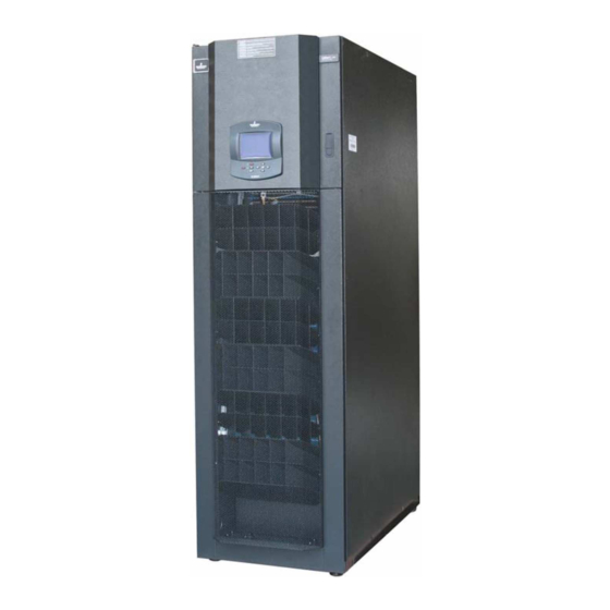
Liebert.CRV Series Air Conditioner
User Manual
Version
V1.4
Revision date
May 28, 2012
BOM
31011886
Emerson Network Power provides customers with technical support. Users may contact
the nearest Emerson local sales office or service center.
Copyright © 2010 by Emerson Network Power Co., Ltd.
All rights reserved. The contents in this document are subject to change without notice.
Emerson Network Power Co., Ltd.
Address: No.1 Kefa Rd., Science & Industry Park, Nanshan District 518057, Shenzhen
China
Homepage: www.emersonnetworkpower.com.cn
E-mail: support@emersonnetwork.com.cn
Advertisement
Table of Contents


Need help?
Do you have a question about the CR020 and is the answer not in the manual?
Questions and answers