Table of Contents
Advertisement
Advertisement
Table of Contents

Related Manuals for Liebert HPS


Summary of Contents for Liebert HPS
- Page 1 H P S SERVICE MANUAL English Cod. 273000 Rev. 16.02.2006 Issued by T.D.Service...
- Page 3 Caution Recommendations: the manual is retained for the entire service life of the machine; the user reads the manual carefully before carrying out any operations on the machine; the machine is used exclusively for the purpose for which it is intended; incorrect use of the machine shall release the manufacturer from any liability.
-
Page 4: Table Of Contents
Index 1 -- Preliminary operations ............. . . pag. -
Page 5: Preliminary Operations
This manual covers the installation, operation and mainten- room ceiling. ance of HPS air conditioners, which are composed of an Fix the unit to the ceiling by inserting expansion or evaporating unit (HPSE), positioned in the room, and a con- through clamps (in this case ensure the clamp is sealed) densing unit (HPSC), positioned outside. -
Page 6: Refrigeration Connections
IMPORTANT: conditions (e.g. in case of temporary abnormal loads on the unit). The bulb must be positioned as much outside as possible but must not be exposed to direct sunlight or weather agents 2.6 --- Refrigeration connections such as rain or snow. The unit operation could be jeopardized THIS OPERATION MUST BE CARRIED OUT BY AN EX- if these precautions are not applied. -
Page 7: Starting And Stopping
The self---test function, per- forms a sequential, automatic check of components such as The standard control system on HPS is based on a micropro- the compressor, fan, heaters, Freecooling damper, alarm cessor board mounted inside the electrical panel, which can relay and warning relay. -
Page 8: Cooling Only Unit
3.4 --- Starting and stopping 4.2 --- Emergency cooling (optional) For the units provided with the POWERFACE control, you 4.2.1 --- Emergency cooling 48VDC can switch on/off using the main switch. With the 48VDC emergency cooling option, the evaporator For the units provided with HIROMATIC interface: fan, freecooling damper actuator and controls are always Start up the unit by pressing the Hiromatic ON---OFF supplied at 48VDC, while the compressor, the condenser fan... -
Page 9: Unit With Freecooling
Fig. b) Unit operation with electrical heating eral units are simultaneously on, with the same Set Point, the temperature used for the control is the average of those de- P Band tected. In mechanical cooling mode, the proportional semi--- Cooling and band is divided by the number of units in the system, in order Band Band... -
Page 10: Routine Maintenance
7 --- Maintenance / Spare parts For safety reasons, always isolate the unit using the mains switch OFF, before opening the panels. If installed: AS THE MICROPROCESSOR CONTROL FEATURES AUTO- On a daily basis, check the control readings for tempera- MATIC RESTART (AFTER A SUPPLY INTERRUPTION), IT IS ture and, if shown, relative humidity. -
Page 11: Spare Parts
7.2.3 --- R407C refrigerant units The oil to be used when topping up is EMKARATE RL 32---3MA or MOBIL EAL ARTIC 22CC, if it’s unavailable use 7.2.3.1---Features of the refrigerating fluid R407C an oil with the same characteristics (see Tab. g and Tab. h). NEVER MIX DIFFERENT OILS TOGETHER. -
Page 12: Check The Unit After The Installation
8 --- Appendix 8.1 --- Check the unit after the installation The following list includes the checks to carry out to verify that HPS is intact after the installation. IMPORTANT: EVERY UNIT IS TESTED IN OUR PLANTS BEFORE DELIVERY. A) STATIC CHECK B) DYNAMIC CHECK A.1) - Page 13 Tab. 1 -- 50 Hz Technical data for “COOLING ONLY” and “COOLING + HEATING” unit versions (F and F + C) coupled with “HPSCxx0” Model HPS 06 HPS 08 Operating limits Main power supply voltage 230V ±10% / 1Ph / 50Hz 400V±10% / 3Ph+N+PE / 50Hz...
- Page 14 Tab. 2 -- 50 Hz Technical data for “FREECOOLING” and “230V/1Ph/50Hz EMERGENCY FREECOOLING” unit versions (FC and EFC-- AC) coupled with “HPSCxx0” Model HPS 06 HPS 08 Operating limits Main power supply voltage 230V ±10% / 1Ph / 50Hz 400V±10% / 3Ph+N+PE / 50Hz 230V ±10% / 1Ph+PE / 50Hz...
- Page 15 Tab. 3 -- 50 Hz Technical data for “FREECOOLING” and “48Vdc EMERGENCY FREECOOLING” unit versions (FC and EFC-- DC) coupled with “HPSCxx0” Model HPS 06 HPS 08 Operating limits Main power supply voltage 230V ±10% / 1Ph / 50Hz 400V±10% / 3Ph+N+PE / 50Hz 48VDC ±17%...
- Page 16 Tab. 4 -- 50 Hz Technical data for ”COOLING ONLY” and “COOLING + HEATING” unit versions (F and F+C) coupled with “HPSCxxA/L ” Model HPS 06 HPS 08 HPS 10 HPS 12 HPS 14 Operating limits 230V ±10% Main power supply voltage 400V ±10% / 3Ph+N+PE / 50Hz...
- Page 17 Tab. 5 -- 50 Hz Technical data for “FREECOOLING” and “230V/1Ph/50Hz EMERGENCY FREECOOLING” unit versions (FC and EFC-- AC) coupled with “HPSCxxA/L ” Model HPS 06 HPS 08 HPS 10 HPS 12 HPS 14 Operating limits 230V ±10% Main power supply voltage 400V ±10% / 3Ph+N+PE / 50Hz...
- Page 18 Tab. 6 -- 50Hz Technical data for “FREECOOLING” and “48Vdc EMERGENCY FREECOOLING” unit versions (FC and EFC-- DC) coupled with “HPSCxxA/L ” Model HPS 06 HPS 08 HPS 10 HPS 12 HPS 14 Operating limits 230V ±10% Main power supply voltage 400V ±10% / 3Ph+N+PE / 50Hz...
- Page 19 “cooling+heating” and “freecooling”) Cable sizing 2 poles 4 poles Unit power supply 230V / 1Ph / 50Hz 400V / 3Ph / 50Hz + N HPS 06 2 x 2.5mm + T x 2.5mm (”C” curve) HPS 08 HPS 08 HPS 10...
- Page 20 Tab. 8 -- Settings Component Setting Notes STOP: 1.0 bar Automatic reset Low pressure switch (LP) START: 2.0 bar (fixed settings) STOP: 28.0 bar Manual reset pressing High pressure switch (HP) START: 20.0 bar the push button (fixed settings) SET: 25.0 bar Fan speed controller (BV) BANDA P: 3.8 bar (only for “HPSCxxA/L ”...
- Page 21 pag. 17...
- Page 22 pag. 18...
- Page 23 pag. 19...
- Page 24 pag. 20...
- Page 25 pag. 21...
- Page 26 pag. 22...
- Page 27 Fig. 2 --- Installation Fig. 2a --- Evaporating unit ceiling installation HPSE 06---08---10---12---14 (version without freecooling) Service area for electical board 803 (HPSE 06--08--10) min. 300 903 (HPSE 12--14) pag. 23...
- Page 28 Fig. 2b --- Evaporating unit installation HPSE 06---08---10---12---14 (version with freecooling) Service area for electical board HPSE min. 300 08---10---12---14 min. 320 min. 300 ITEM DESCRIPTION Electrical box accessibility Support for filter Air filter Freecooling filter accessibility Electrical box pag. 24...
- Page 29 Fig. 2c --- Evaporating unit ceiling installation HPSE 06---08---10---12---14 (version with freecooling) CODE CODE ITEM DESCRIPTION HPSE 06 HPSE 08---10---12---14 Wall plate for circular ducts 13503801 13536101 2 flexible ducts with fixing clamps, L = 0.5 m 270190 (Ø 202mm) 270191 (Ø...
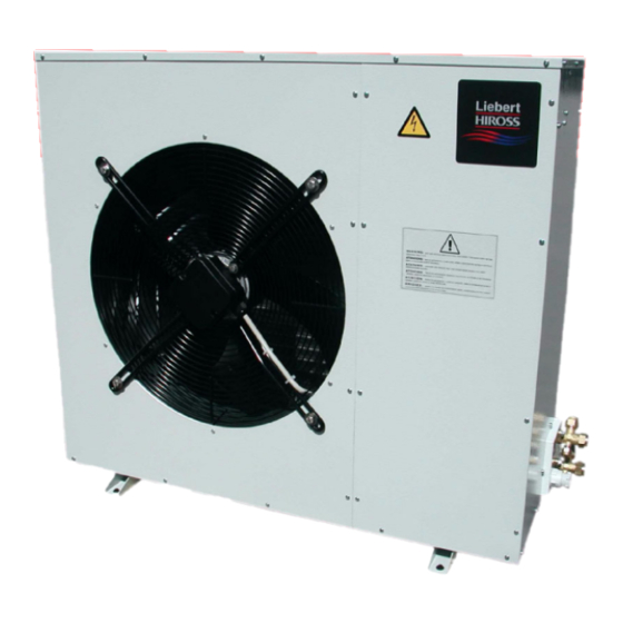
- Page 30 Fig. 2d --- Condensing unit wall installation HPSC 06---08 COD. 129201 HPSC 10---12---14 KIT DESCRIPTION ITEM COD. 129201 Serrated lock washer Washer Anti--- vibrating mount Bracket pag. 26...
- Page 31 Fig. 3 --- Condenser positions pag. 27...
- Page 32 Fig. 4 --- Service area HPSC 06---08---10---12---14 WALL IN FRONT OF UNITS WALL IN FRONT OF UNITS WALL BEHIND WALL BEHIND UNITS UNITS MULTI---ROWS INSTALLATION If H1 < 0.5 x H2 ..⇒...
- Page 33 Fig. 5 --- Electric connections HPSE (optional) HPSC Remote display AC power supply DC power supply (optional) AC line input SC unit control HPSC Powerface display No. 2 cable clips PG21 AC line input No. 2 cable clips PG21 Auxiliary input HPSE AC line output for HPSC condensing unit...
- Page 34 pag. 30...
- Page 35 pag. 31...
- Page 36 pag. 32...
- Page 37 CN10 Board TM 48 --- A2 Faston 6.3 Fuse 1A--- F CN 4 CN 2 pag. 33...
- Page 38 Fig. 8 --- Operating diagram Fig. 8a --- Operating diagram (without freecooling) Return CROSS SECTION Return air Treated air ITEM DESCRIPTION Evaporating coil TOP VIEW (WITHOUT PANEL) Fig. 8b --- Operating diagram (with freecooling) Return Freecooling CROSS Freecooling air SECTION Return air Treated air ITEM...
- Page 39 Fig. 9 --- HPS 06---08 (HPSCxx0) --- Refrigerating diagram Internal unit Supplying Connection pipe limit External unit ITEM DESCRIPTION Compressor Crankcase heater High pressure switch (HP) Air cooled condenser Weld joint Access valve Filter dryer Expansion capillary Evaporator Low pressure switch (LP)
- Page 40 Fig. 10 --- HPS 06---08---10---12---14 (HPSCxxA/L) --- Refrigerating diagram Internal unit Supplying Connection pipe limit HPC 14 External unit ITEM DESCRIPTION Compressor Crankcase heater High pressure switch (HP) Air cooled condenser Weld joint Access valve Evaporator fan Filter dryer Sight glass (FG)
- Page 41 Fig. 11 --- Suggested refrigerant connections (HPSCxx0/A + HPSE) Gas pipeline (Sloping 1%) HPSE Liquid pipeline HPSC (Internal Unit) (External Unit) 10 m max. horizontal equivalent length Syphons (obligatory) Gas pipeline (Sloping 1%) HPSC (External Unit) Gas pipeline (Sloping 1%) HPSE (Internal Unit) Liquid pipeline...
- Page 42 Fig. 12 --- Suggested refrigerant connections (HPSCxxL + HPSE) Gas pipeline (Sloping 1%) HPSE Liquid pipeline HPSC (Internal Unit) (External Unit) 50 m max. horizontal equivalent length Syphons (obligatory) Gas pipeline (Sloping 1%) HPSC (External Unit) Gas pipeline (Sloping 1%) HPSE (Internal Unit) Liquid pipeline...
- Page 43 Produsent erklærer herved at dette produktet er i samsvar med EU-direktiver: Fabrikant erklærer herved, at dette produkt opfylder kravene i EU direktiverne: Since the Liebert HIROSS Company has a policy of continuous Ο ΚατασÀευαστÞj δηλþνει üτι το παÃüν πÃοΪüν εßναι ÀατασÀευασmÝνο αýmφωνα mε τιj οδηγßεj τηj Ε.Ε.: product improvement, it reserves the right to change design and specifications without previous notice.
- Page 44 Tel. +39 049 9719111 Telefax +39 049 5841257 Internet : www.liebert-hiross.com Liebert HIROSS Since the Liebert HIROSS Company has a policy of continuous is a division of product improvement, it reserves the right to change design and EMERSON specifications without previous notice.
Need help?
Do you have a question about the HPS and is the answer not in the manual?
Questions and answers