Advertisement
Available languages
Available languages
Quick Links
SAFETY INSTRUCTIONS
KEEP THESE INSTRUCTIONS
Warning: If fixture is installed less than 1.5m (5 ft) from the inside walls of the pool it must be supplied by
a listed transformer or power supply that complies with NEC article 680.23 (A) (2).
This fixture is intended for installation in accordance with the National Electric Code (NEC) and Local code
specifications. Failure to adhere to these codes and instructions may result in serious injury and/or property
damage and will void the warranty.
1) WARNING: This fixture is not to be installed within 10 feet (3M) of a pool, spa or fountain.
2) According to the requirements of the National Electric Code (NEC), direct burial rated wire is to be buried a
minimum of 6" [152mm] beneath the surface of the ground.
NOTE: If additional Direct Burial wire is needed, contact your local Kichler
• 8 GA wire can be purchased in length of 250' (76 M),15503-BK.
• 10 GA wire can be purchased in length of 250' (76 M),15504-BK.
• 12 GA wire can be purchased in lengths of 100' (30 M),15501-BK; 250' (76 M), 15502-BK; 500' (152M),
15505-BK; and 1000' (304 M), 15506-BK.
3) Wiring connections must be made with approved/listed wire connection device(s) suitable for the application. Do
not exceed manufacturers' wiring combination specifications for size and quantity of conductors.
WHEN INSTALLING KICHLER LANDSCAPE LIGHTING (LINE VOLTAGE OR LOW VOLTAGE), CARE SHOULD BE TAKEN TO
KEEP CLEAR OF POTENTIALLY COMBUSTIBLE MATERIALS.
WHEN MAINTAINING THE FIXTURES, BE SURE TO REMOVE LEAVES, PINE NEEDLES, GRASS CLIPPINGS, MULCH, OR ANY
DEBRIS THAT HAS ACCUMULATED ON THE LIGHT BULB, LENS, OR BODY OF THE FIXTURE.
ASSEMBLY AND INSTALLATION
1) Determine desired location for mounting fixture.
2) At desired location, hammer stake into ground. To avoid damage to stake, place a board on top of
stake while hammering. If ground is hard and stake is difficult to install, make a crosscut in ground
using a flat shovel.
3) Clear away area in ground at wireway slot in top of stake.
4) Lay 12V cable into wireway slot and screw fixture into stake. Aim fixture in desired direction and
secure by tightening locknut. If necessary, use wrench or pliers for final tightening of nut.
5) Adjust angle of accent light by loosening Phillips head screw.
6) Adjust angle of cowl by loosening thumb screw.
7) TURN OFF POWER.
8) Make wire connections using supplied wire connectors following instructions included, or using
other approved wiring connection method (not supplied).
TO CHANGE LIGHT OUTPUT SETTING:
•
NOTE: Fixure switches up in terms of lumen settings; it starts at medium (200 lumens) for the small
accent and starts at low (400 lumens) for the large accent. If these levels are desired, no adjustment
is needed.
•
Locate the dimple at the top of the fixture. (This is called a lumen adjustment switch locator)
•
Hold magnet on lumen adjustment switch locator for 1.5 seconds to begin programming mode.
Remove magnet.
•
Fixture will blink continuously 4x's at full brightness level and go dark for 2 seconds and then will
illuminate at original factory setting.
•
To switch lumen settings, magnet must be reapplied to lumen adjustment switch locator for 1.5
seconds and magnet must be removed for 1 second between switching.
•
NOTE: fixture blinks 1x for the lowest lumen setting; 2x's for the middle lumen setting, and 3x's for
the highest lumen setting.
•
Once the fixture is set and magnet removed, it stays in programming mode for 2 minutes.
•
After 2 minutes, the memory is set.
•
To change the output brightenss, return to programming mode by holding magnet on magnetic
locator for 1.5 seconds.
•
NOTE: Fixture reverts back to original factory setting when put back into programming mode.
Wire
G auge/Power/Length
C hart
Wire
G auge/Length
( ft/m)
p er
r un
WATTS
( VA)
10
0
-‐
2 0
1860/567
40
930/283
60
620/189
80
470/143
100
370/113
C onsult
T echnical
S upport
>100
Fixture
L oad
C hart
Fixture
Lumen
AC
V oltage
( VA)
Style
Level
9V
Large
3
23
Large
2
16
Large
1
9
Small
3
7.5
Small
2
5.5
Small
1
3.5
NOTE: When sizing your transformer please use the highest VA you
expect to use depending on desired lumen level to prevent potentially
overloading the transformer.
Date Issued: 02/07/18
READ THIS FIRST
®
landscape distributor.
CAUTION
12
14
16
1150/351
730/223
450/137
580/177
370/113
230/70
390/119
240/73
150/46
290/88
180/55
110/34
230/70
140/43
90/27
DC
V oltage
( W)
12V
15V
9V
12V
22.5
22.5
18.5
16.5
15.5
15.5
12.5
11
9
9
7
6
7.5
8
5.5
5.5
5.5
5.5
3.5
3.5
3.5
3.5
2
2
For warranty information please visit: http://www.landscapelighting.com/portal/warranty_page
Para informacion de la garantia por favor visite: www.landscapelighting.com/portal/warranty_page
LUMEN ADJUSTMENT
SWITCH LOCATOR
Small
A ccent
16015-‐ 1 6017
Large
A ccent
16018-‐ 1 6020
LUMEN ADJUSTMENT
SWITCHING
SWITCH LOCATOR
MAGNET
15V
16
11
6
5.5
3.5
2
We're here to help 866-558-5706
Hrs: M-F 9am to 5pm EST
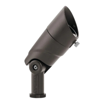
FIXTURE
PHILLIPS HEAD SCREW TO
ADJUST ANGLE OF FIXTURE
LOCKNUT
STAKE
WIRE LEADS
PROGRAMMING MODE
Gen
3
L umen
T able
f or
I S
-‐
0 5112017.xlsx
Lumen
L evel
T able
( For
2 700K/3000K)
Level
1
Level
2
Level
3
100
L m
*200
L m
300
L m
*400
L m
600
L m
835
L m
* DENOTES FACTORY SETTING
THUMB SCREW TO AD-
JUST ANGLE OF COWL
OR TO LOOSEN AND
REMOVE COWL
SWITCHING
MAGNET
ORIGINAL
PROGRAMMING MODE
LEVEL 1
LEVEL 2
Confidential
LEVEL 3
IS-16015-US
Advertisement

Related Manuals for Kichler Lighting 16015


Summary of Contents for Kichler Lighting 16015
- Page 1 To switch lumen settings, magnet must be reapplied to lumen adjustment switch locator for 1.5 Small A ccent seconds and magnet must be removed for 1 second between switching. 16015-‐ 1 6017 100 L m *200 L m 300 ...
- Page 2 1,5 seconde et l’aimant doit être retiré pendant 1 seconde entre la Accent P etit commutation. *200 L m 16015-‐16017 100 L m 300 L m • REMARQUE : l’appareil clignote 1 fois pour le réglage de luminosité le plus faible ; 2 fois pour le réglage de la luminosité...
- Page 3 Mantenga el imán en el localizador del interruptor de ajuste del lumen durante 1.5 segundos para empezar Acentuación P equeña el modo de programación. Remueva el imán. 16015-‐16017 100 L m *200 L m 300 L m •...
Need help?
Do you have a question about the 16015 and is the answer not in the manual?
Questions and answers