Advertisement
Available languages
Available languages
Table of Contents
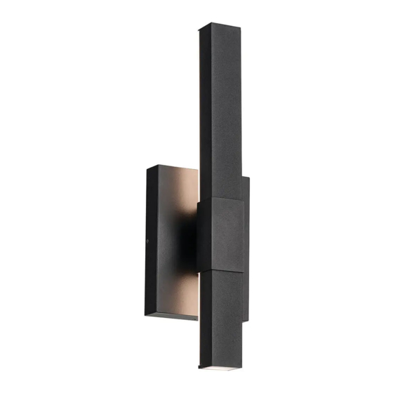
FIXTURE DIAGRAM
PARTS LIST
[A] Plate Mounting Screw (2)
[B] Outlet Box (not supplied)
CAUTIONS
CAUTION – RISK OF SHOCK:
Disconnect Power at the main circuit breaker panel or main fusebox before starting and during
the installation.
WARNING:
1. This fixture is intended for installation in accordance with the National Electrical Code (NEC)
and all local code specifications. If you are not familiar with code requirements, installation by a
certified electrician is recommended. Failure to adhere to these codes and instructions may result
in serious injury and/or property damage and will void the warranty.
INSTRUCTIONS FOR MOUNTING FIXTURE OUTDOORS
AND/OR IN WET LOCATIONS:
1) Mounting surface should be clean, dry, flat and 1/4" larger than the canopy on all sides. Any gaps
between the mounting surface and canopy exceeding 3/16" should be corrected as required.
2) With silicone caulking compound, caulk completely around where back of canopy meets the wall
surface to prevent water from seeping into outlet box.
DIMMING:
This LED fixture is compatible with most standard incandescent dimmers, LED dimmers, and
electronic low voltage dimmers.
For optimal performance, an electronic low voltage dimmer should be used.
See kichler.com/dimming for a list of compatible dimmers.
CLEANING:
• Always be certain that electric current is turned off before cleaning.
• Only a soft damp cloth should be used. Harsh cleaning products may damage the finish.
REV 7-MAR-2023
C
A
G
D
E
C
Fig. 1
MOUNTING PLATE [C]
(VERTICAL ORIENTATION)
[C] Mounting Plate
[D] Drainage Hole
[E] Set Screw (2)
© 2023 Kichler Lighting LLC. All rights reserved.
For warranty information please visit: kichler.com/warranty
B
F
Fig. 2
ALLEN WRENCH [F]
(INCLUDED)
[F] Allen Wrench
[G] Canopy
We're here to help
INSTALLATION INSTRUCTIONS
1.
Attach mounting plate[C] to outlet box[B] using the plate mounting
screws[A]. Mounting plate should be installed in a vertical orientation
ONLY (Fig. 1), and with the flat side of the mounting plate facing toward
the outlet box (as shown).
2.
Grounding instructions: (See Illus. a or b).
a.
On fixtures where mounting plate is provided with a hole and two
raised dimples, wrap ground wire from outlet box around green
ground screw, and thread into hole.
b.
On fixtures where a cupped washer is provided, attach ground wire
from outlet box under cupped washer and green ground screw, and
thread into mounting plate.
If fixture is provided with ground wire, connect fixture ground wire to
outlet box ground wire with wire connector after following the above
steps. Never connect ground wire to black or white power supply wires.
a
WIRE CONNECTOR
OUTLET BOX
GROUND
FIXTURE
GROUND
OUTLET BOX
DIMPLES
GROUND
GREEN GROUND
SCREW
3.
Make wire connections. Reference chart below for correct connections
and wire accordingly.
Connect Black or Red
Supply Wire to:
Black
*Parallel cord (round &
smooth)
Clear, Brown, Gold or Black
without Tracer
Insulated wire (other
than green) with copper
conductor
*Note: When parallel wire (SPT
1 & SPT 2) are used. The neutral
wire is square shaped or ridged
and the other wire will be round
in shape or smooth (See illus.)
4.
NOTE: Fixture should be installed with the drainage hole[D] in the
canopy facing DOWN (as shown).
Push canopy[G] to wall, carefully aligning the mounting screw holes in the
left and right side of canopy with the angled indents in the left and right
side of mounting plate.
NOTE: Make sure all wires are inside canopy and do not get pinched
between mounting plate and canopy or wall and canopy of fixture.
5.
While holding fixture in place, screw two (2) set screws[E] into holes in
canopy (one on the left side and one on the right side of canopy) using
Allen wrench[F] (Fig. 2). Tighten set screws against mounting plate to
secure fixture to wall.
FCC INFORMATION
This device complies with part 15 of the FCC Rules. Operation is subject to the following two
conditions:
1.
This device may not cause harmful interference, and
2.
This device must accept any interference received, including interference that may
cause undesired operation.
Note: This equipment has been tested and found to comply with the limits for a Class B
digital device, pursuant to part 15 of the FCC Rules. These limits are designed to provide
reasonable protection against harmful interference in a residential installation. This
equipment generates, uses and can radiate radio frequency energy and, if not installed
and used in accordance with the instructions, may cause harmful interference to radio
communications. However, there is no guarantee that interference will not occur in a
particular installation. If this equipment does cause harmful interference to radio or
television reception, which can be determined by turning the equipment off and on, the
user is encouraged to try to correct the interference by one or more of the following
measures:
•
Reorient or relocate the receiving antenna.
•
Increase the separation between the equipment and receiver.
•
Connect the equipment into an outlet on a circuit different from that to which the
receiver is connected.
•
Consult the dealer or an experienced radio/TV technician for help.
866-558-5706
Hrs: M-F 9am to 5pm EST
b
FIXTURE
GROUND
GREEN GROUND
CUPPED
WASHER
SCREW
Connect White Supply
Wire to:
White
*Parallel cord (square &
ridged)
Clear, Brown, Gold or Black
with Tracer
Insulated wire (other
than green) with silver
conductor
Neutral Wire
IS-59143-US
Advertisement
Table of Contents

Subscribe to Our Youtube Channel
Related Manuals for Kichler Lighting Nocar 59143BKT


Summary of Contents for Kichler Lighting Nocar 59143BKT
- Page 1 • Always be certain that electric current is turned off before cleaning. • Only a soft damp cloth should be used. Harsh cleaning products may damage the finish. © 2023 Kichler Lighting LLC. All rights reserved. For warranty information please visit: kichler.com/warranty...
- Page 2 • Soyez toujours certain que l’alimentation électrique du luminaire est fermée avant le nettoyage. • N’utilisez qu’un chiffon doux humide. Les produits de nettoyage acides/abrasifs peuvent endommager le fini. © 2023 Kichler Lighting LLC. Tous droits réservés. Pour de plus amples informations sur la garantie, veuillez visiter : kichler.com/warranty REV 7-MAR-2023...
- Page 3 • Asegúrese siempre de que la corriente eléctrica esté apagada antes de limpiar. • Debe usarse solamente un paño húmedo y suave. Productos de limpieza abrasivos pueden dañar el acabado. © 2023 Kichler Lighting LLC. Todos los derechos reservados. Para informacion de la garantia por favor visite: kichler.com/warranty REV 7-MAR-2023...
Need help?
Do you have a question about the Nocar 59143BKT and is the answer not in the manual?
Questions and answers