Table of Contents
Advertisement
Quick Links
Advertisement
Table of Contents

Related Manuals for SteppIR SY3


Summary of Contents for SteppIR SY3
- Page 1 SY3 System Users Manual Manual REV 1.2 March 15th 2024...
-
Page 2: Table Of Contents
TABLE OF CONTENTS General Safety Summary SY3 System Assembly Section 1: SY3 Stand Section 2: SY3 Antenna 7-10 Section 3: Receive Antenna and Stand 11-12 SY3 System User Guide Section 4: Theory of Operation Section 5: Setup For Hardware for Tuning... -
Page 3: General Safety Summary
Connect the Antenna Correctly When connecting the SY3 Antenna to the SY3 Analytics Tower, ensure that all connections are fastened se- curely. Utilize both screws on the DB-25 connecter to prevent accidental disconnection of the cable during use. - Page 4 Observe Antenna Power Ratings The SY3 antenna is rated to 2500 Watts at 2.5 : 1 VSWR. Operating at higher RF power or higher VSWR values can result in damage to the system. Burn Prevention The SY3 Antenna enclosure underside surface may be hot during and immediately after transmitting.
-
Page 5: Sy3 System Assembly
Section 1: The SY3 Stand allows for quick levelling and adjustments of the SY3 Antenna. It uses a PanaVise head to tilt the SY3 Antenna between horizontal and vertical polarizations, as well as four leveling feet for fine tuned con- trol. - Page 6 SY3 SYSTEM ASSEMBLY: SY3 STAND Using a 3/16” hex (Allen) key, secure the four legs by tightening the set screws as shown in Figure 2. Ensure that the leveling feet are facing the ground as shown in Figure 1 on the previous page before tightening.
-
Page 7: Section 2: Sy3 Antenna
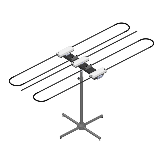
SY3 SYSTEM ASSEMBLY: SY3 ANTENNA Section 2: The SY3 Antenna boom is attached to the PanaVise mount using four Phillips head screws. These screws are fastened into the SY3 Antenna boom during shipping. Remove the four mounting screws from the bottom of the antenna boom, as shown in Figure 3. - Page 8 SY3 SYSTEM ASSEMBLY: SY3 ANTENNA Remove the two black plastic thumbscrews on the center element, and insert a straight element fiberglass support tube into each side of the center element, as shown in Figure 5. Make sure each fiberglass support is fully seated within the element.
- Page 9 SY3 SYSTEM ASSEMBLY: SY3 ANTENNA Remove the four black plastic thumbscrews on the front element and gray return support block, insert a fold- ed element fiberglass support assembly into each side of the elements, as shown in Figure 6. The folded ele- ment fiberglass supports are not symmetrical, please refer to Figure 7 on the next page for the correct orien- tation.
- Page 10 SY3 SYSTEM ASSEMBLY: SY3 ANTENNA Folded Element Long Side Folded Element Short Side Figure 7 13406 SE 32nd St, BELLEVUE WA, 98005 WWW.STEPPIR.COM TEL: (425)-453-1910...
-
Page 11: Section 3: Receive Antenna And Stand
SY3 SYSTEM ASSEMBLY: RECEIVE ANTENNA AND STAND Section 3: The SY3 System uses a 0.03—1 GHz Biconical Antenna and non-conductive stand to measure and optimize for signal strength while tuning. Figure 8 demonstrates how the non-conductive stand is assembled Figure 8 13406 SE 32nd St, BELLEVUE WA, 98005 WWW.STEPPIR.COM... - Page 12 SY3 SYSTEM ASSEMBLY: RECEIVE ANTENNA AND STAND Fasten the Receive Antenna to the stand’s horizontal arm using the black plastic thumbscrew, as shown in Figure 9. Adjust the Receive Antenna position and counterweight as needed. Figure 9 13406 SE 32nd St, BELLEVUE WA, 98005 WWW.STEPPIR.COM...
-
Page 13: Sy3 System User Guide
E-field probe would be placed, 10cm inset from the edge of the bench (1m from center of receive antenna to center of the first element on the SY3 Antenna), and 30cm above the surface of the bench. -
Page 14: Section 5: Setup For Hardware For Tuning
3. The analytics tower and cables The SY3 Antenna The SY3 Antenna should be placed inside of the EMC chamber 90cm from the edge of the bench, and cen- tered on the bench, as described in MIL-STD-461G, RS 103. This measurement should be taken from the center of the front element fiberglass support tube. - Page 15 Antenna as shown in Figure 14. We recommend that the Receive Antenna should also be positioned 61cm (24") to the right of the centerline of the SY3 Antenna when in horizontal polarization as shown in Figure 15 on the next page. In vertical polarization the Receive Antenna should be positioned on the centerline of the SY3 Antenna as shown in Figure 14.
- Page 16 “ANTENNA” or “OUTPUT” port (depending on the version of the Analytics Tower) on the OptimizIR EMC. Double check these connections! If the SY3 Antenna is being used in a new location, it is necessary to create a new “Antenna Configu- ration” for both the Horizontal and Vertical Polarization.
-
Page 17: Section 6: User Interface Overview
SY3 SYSTEM USER GUIDE: USER INTERFACE OVERVIEW Section 6: Creating, selecting, and modifying an antenna configuration is done using the OptimizIR EMC on the Analytics Tower. After the device is powered on, you will see the interface shown in Figure 16. -
Page 18: Section 7: Starting A Tune
Figure 17. Horizontal and Vertical Presets use different parameters when tuning the SY3 System. Select- ing an incorrect preset for your antenna’s polarization can lead to poor antenna performance! Figure 17 Press the “TUNE NEW”... - Page 19 SY3 SYSTEM USER GUIDE: STARTING A TUNE Figure 18 Figure 19 13406 SE 32nd St, BELLEVUE WA, 98005 WWW.STEPPIR.COM TEL: (425)-453-1910...
-
Page 20: Section 8: Setup For Testing
103 test. They are not rated to the 2500W power limit of the system. It is the customers responsibility to use a coaxial cable for the SY3 Antenna during the RS 103 test that is suitable for at least 2500W in the 30-200MHz frequency range. -
Page 21: Section 9: Manually Testing
Section 9: If you do not have the SY3 system integrated with TILE! or your own proprietary testing software, you will need to perform the test manually. In order to perform the test manually you will need to send the antenna to a test frequency, apply RF power to the antenna at the correct frequency, measure the E-field, turn off RF power to the antenna, then send the antenna to the next test frequency, and repeat. - Page 22 SY3 SYSTEM USER GUIDE: MANUALLY TESTING Select the appropriate frequency using the dropdown shown in Figure 21. You can also change frequencies by clicking the “<<“ or “>>“ buttons shown below. Move down one frequency Move up one frequency Figure 21 13406 SE 32nd St, BELLEVUE WA, 98005 WWW.STEPPIR.COM...
- Page 23 “Retracted”. Figure 22 When “SEND TO ANTENNA” is clicked, the interface will show that the SY3 Antenna is adjusting (Figure 23), then will show the new Configuration and Frequency on the Status Menu when done (Figure 24). The Status Menu can only track the SY3 Antenna element lengths while the OptimizIR EMC is pow- ered on.
- Page 24 SY3 SYSTEM USER GUIDE: MANUALLY TESTING Figure 23 Figure 24 13406 SE 32nd St, BELLEVUE WA, 98005 WWW.STEPPIR.COM TEL: (425)-453-1910...
- Page 25 SY3 SYSTEM USER GUIDE: MANUALLY TESTING Now that the SY3 Antenna has been sent to a test frequency, it is time to apply RF power to the system. It is recommended to start off applying low RF power (100W) to verify that the antenna has lower than 2.5 : 1 VSWR.
- Page 26 13406 SE 32nd St, BELLEVUE WA, 98005 WWW.STEPPIR.COM TEL: (425)-453-1910...
Need help?
Do you have a question about the SY3 and is the answer not in the manual?
Questions and answers