Table of Contents
Advertisement
Quick Links
TPS65283EVM-646 and TPS65283-1EVM-646 3.5-A, 2.5-A
Regulator and Power Switch Evaluation Module
This document presents the information required to power the TPS65283 and TPS65283-1 power-
management integrated circuits (PMIC) as well as the support documentation including schematic, printed-
circuit board (PCB) layout, and bill of materials (BOM). Throughout the remainder of this document, the
abbreviations EVM, TPS65283/-1EVM-646, and evaluation module refer to both the TPS65283EVM-646
and TPS65283-1EVM-646. Also throughout this user guide, the abbreviation TPS65283/-1 refers to both
the TPS65283 and TPS65283-1 ICs.
...................................................................................................................
1
2
3
4
4.1
4.2
4.3
5
6
7
1
TPS65283/-1EVM-646 Schematic
2
.....................................................................................................................
3
4
5
6
7
1
2
Jumpers and Switches
3
Test Points and Placement
4
Bill of Materials
SLVUA70 - June 2014
Submit Documentation Feedback
.........................................................................................
.................................................................................................................
..............................................................................................
.............................................................................................
........................................................................................
........................................................................................................
..................................................................................................................
...............................................................................................................
.........................................................................................
.......................................................................................
.........................................................................................................
.................................................................................................................
......................................................................................................
.................................................................................................
...............................................................................................................
TPS65283EVM-646 and TPS65283-1EVM-646 3.5-A, 2.5-A Regulator and
Copyright © 2014, Texas Instruments Incorporated
Contents
....................................................................
List of Figures
............................................................................
............................................................................
List of Tables
.............................................................................
User's Guide
SLVUA70 - June 2014
Power Switch Evaluation Module
2
3
4
6
6
6
7
7
7
8
3
4
5
5
5
5
6
2
6
7
8
1
Advertisement
Table of Contents

Related Manuals for Texas Instruments TPS65283EVM-646


Summary of Contents for Texas Instruments TPS65283EVM-646
-
Page 1: Table Of Contents
(PCB) layout, and bill of materials (BOM). Throughout the remainder of this document, the abbreviations EVM, TPS65283/-1EVM-646, and evaluation module refer to both the TPS65283EVM-646 and TPS65283-1EVM-646. Also throughout this user guide, the abbreviation TPS65283/-1 refers to both the TPS65283 and TPS65283-1 ICs. -
Page 2: Background
Please contact TI Field Applications Group for advice on these matters. TPS65283EVM-646 and TPS65283-1EVM-646 3.5-A, 2.5-A Regulator and SLVUA70 – June 2014... -
Page 3: Tps65283/-1Evm-646 Schematic
AGND TPS65283/ TPS65283-1 10uF TP14 TP10 TP11 TP12 TP13 VOUT2 SH-JP1 SW_IN Figure 1. TPS65283/-1EVM-646 Schematic SLVUA70 – June 2014 TPS65283EVM-646 and TPS65283-1EVM-646 3.5-A, 2.5-A Regulator and Power Switch Evaluation Module Submit Documentation Feedback Copyright © 2014, Texas Instruments Incorporated... -
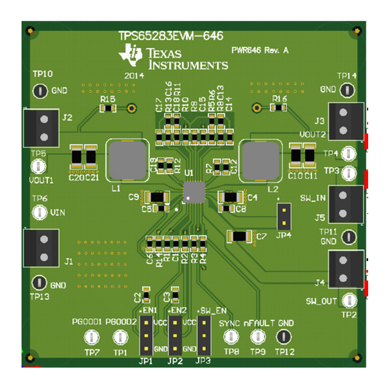
Page 4: Board Layout
Figure 2 through Figure 6 show the PCB board layouts. Figure 2. Component Placement (Top Layer) TPS65283EVM-646 and TPS65283-1EVM-646 3.5-A, 2.5-A Regulator and SLVUA70 – June 2014 Power Switch Evaluation Module Submit Documentation Feedback Copyright © 2014, Texas Instruments Incorporated... -
Page 5: Top Layer
Figure 4. Middle (Second) Layer Solid Copper Figure 3. Top Layer Ground Figure 6. Bottom Layer Figure 5. Middle (Third) Layer SLVUA70 – June 2014 TPS65283EVM-646 and TPS65283-1EVM-646 3.5-A, 2.5-A Regulator and Power Switch Evaluation Module Submit Documentation Feedback Copyright © 2014, Texas Instruments Incorporated... -
Page 6: Bench Test Setup Conditions
To disable SWITCH fit jumper to GND requirement Vout2 to SW_IN SW_IN pull to Vout2 Fit according to test requirement TPS65283EVM-646 and TPS65283-1EVM-646 3.5-A, 2.5-A Regulator and SLVUA70 – June 2014 Power Switch Evaluation Module Submit Documentation Feedback Copyright © 2014, Texas Instruments Incorporated... -
Page 7: Test Points And Placement
TPS65283/-1 (SLVSCL3) data sheet's application curves. All the data and waveforms are tested based on this EVM board. SLVUA70 – June 2014 TPS65283EVM-646 and TPS65283-1EVM-646 3.5-A, 2.5-A Regulator and Power Switch Evaluation Module Submit Documentation Feedback... -
Page 8: Bill Of Materials
Test Point, Miniature, Black, TH QFN-24 4.5 V to 18 V Input Voltage, Maximum 3.5A/2.5A Current, Synchronous Dual Buck Converter with Power Distribution Switch, RGE0024B TPS65283EVM-646 and TPS65283-1EVM-646 3.5-A, 2.5-A Regulator and SLVUA70 – June 2014 Power Switch Evaluation Module Submit Documentation Feedback... - Page 9 ADDITIONAL TERMS AND CONDITIONS, WARNINGS, RESTRICTIONS, AND DISCLAIMERS FOR EVALUATION MODULES Texas Instruments Incorporated (TI) markets, sells, and loans all evaluation boards, kits, and/or modules (EVMs) pursuant to, and user expressly acknowledges, represents, and agrees, and takes sole responsibility and risk with respect to, the following: 1.
- Page 10 RADIO FREQUENCY REGULATORY COMPLIANCE INFORMATION FOR EVALUATION MODULES Texas Instruments Incorporated (TI) evaluation boards, kits, and/or modules (EVMs) and/or accompanying hardware that is marketed, sold, or loaned to users may or may not be subject to radio frequency regulations in specific countries.
- Page 11 Les types d'antenne non inclus dans cette liste, ou dont le gain est supérieur au gain maximal indiqué, sont strictement interdits pour l'exploitation de l'émetteur. Mailing Address: Texas Instruments, Post Office Box 655303, Dallas, Texas 75265 Copyright © 2014, Texas Instruments Incorporated spacer Important Notice for Users of EVMs Considered “Radio Frequency Products”...
- Page 12 IMPORTANT NOTICE Texas Instruments Incorporated and its subsidiaries (TI) reserve the right to make corrections, enhancements, improvements and other changes to its semiconductor products and services per JESD46, latest issue, and to discontinue any product or service per JESD48, latest issue.
Need help?
Do you have a question about the TPS65283EVM-646 and is the answer not in the manual?
Questions and answers