Table of Contents
Advertisement
Quick Links
4.5-V to 18-V Input, Dual (6.5-A and 3.5-A) Synchronous
Step-Down Converter With I
This document is provided with the TPS65276V PMIC evaluation module (EVM) as a supplement to the
TPS65276V datasheet. This user's guide includes the schematic, hardware setup, software installation
and bill of materials (BOM).
1
2
3
4
5
5.1
5.2
5.3
5.4
5.5
6
7
1
TPS65276V Schematic
2
3
4
5
6
7
Header Description and Jumper Placement
8
USB Interface Adapter Quick Connection Diagram
9
Screen Capture of TPS65276V Software GUI Interface
1
2
3
4
TPS65276V EVM Bill of Materials
Windows, Microsoft, Internet Explorer are registered trademarks of Microsoft Corporation.
VeriSign is a trademark of VeriSign, Inc.
SLVU878 - February 2013
Submit Documentation Feedback
..................................................................................................................
..................................................................................................................
.....................................................................................................
................................................................................................................
.............................................................................................
............................................................................................
....................................................................................................
.................................................................................................
...............................................................................................
......................................................................................................
.......................................................................................
.....................................................................................................
......................................................................................
..................................................................................................
.............................................................................................
................................................................................................
..............................................................................................
..................................................................................................
...................................................................................................
.....................................................................................................
.......................................................................................
Converter With I
Copyright © 2013, Texas Instruments Incorporated
2
C Controlled VID and Current
Sharing Evaluation Module
Contents
....................................................................
List of Figures
.............................................................................
....................................................................
.............................................................
List of Tables
4.5-V to 18-V Input, Dual (6.5-A and 3.5-A) Synchronous Step-Down
2
C Controlled VID and Current Sharing Evaluation Module
User's Guide
SLVU878 - February 2013
2
2
3
4
7
7
8
8
9
10
11
12
3
4
5
5
6
6
7
9
10
2
7
8
12
1
Advertisement
Table of Contents

Related Manuals for Texas Instruments TPS65276V PMIC


Summary of Contents for Texas Instruments TPS65276V PMIC
-
Page 1: Table Of Contents
C Controlled VID and Current Sharing Evaluation Module This document is provided with the TPS65276V PMIC evaluation module (EVM) as a supplement to the TPS65276V datasheet. This user's guide includes the schematic, hardware setup, software installation and bill of materials (BOM). -
Page 2: Introduction
Background The TPS65276V PMIC is designed to provide dual (6.5 A and 3.5 A) continuous currents with an operational range of 4.5 to 18 V. The TPS65276V features I... -
Page 3: Tps65276V Schematic
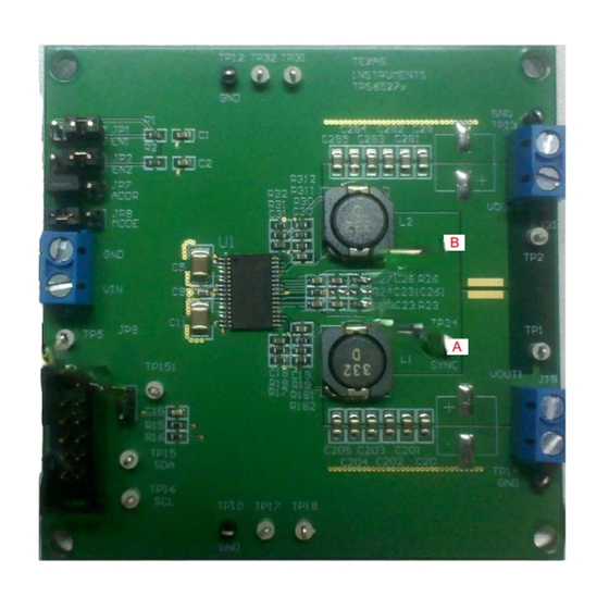
TPS65276V Schematic www.ti.com TPS65276V Schematic Figure 1 shows the TPS65276V PMIC EVM schematic. Figure 1. TPS65276V Schematic SLVU878 – February 2013 4.5-V to 18-V Input, Dual (6.5-A and 3.5-A) Synchronous Step-Down Converter Submit Documentation Feedback With I C Controlled VID and Current Sharing Evaluation Module... -
Page 4: Board Layout
Figure 2. Component Placement (Top Layer) 4.5-V to 18-V Input, Dual (6.5-A and 3.5-A) Synchronous Step-Down SLVU878 – February 2013 Converter With I C Controlled VID and Current Sharing Evaluation Module Submit Documentation Feedback Copyright © 2013, Texas Instruments Incorporated... -
Page 5: Board Layout (Top Layer)
Figure 4. Board Layout (Second Layer) SLVU878 – February 2013 4.5-V to 18-V Input, Dual (6.5-A and 3.5-A) Synchronous Step-Down Submit Documentation Feedback Converter With I C Controlled VID and Current Sharing Evaluation Module Copyright © 2013, Texas Instruments Incorporated... -
Page 6: Board Layout (Third Layer)
Figure 6. Board Layout (Bottom Layer) 4.5-V to 18-V Input, Dual (6.5-A and 3.5-A) Synchronous Step-Down SLVU878 – February 2013 Converter With I C Controlled VID and Current Sharing Evaluation Module Submit Documentation Feedback Copyright © 2013, Texas Instruments Incorporated... -
Page 7: Bench Test Setup Conditions
Output of Buck1 Buck2 Connector Output of Buck2 SLVU878 – February 2013 4.5-V to 18-V Input, Dual (6.5-A and 3.5-A) Synchronous Step-Down Submit Documentation Feedback Converter With I C Controlled VID and Current Sharing Evaluation Module Copyright © 2013, Texas Instruments Incorporated... -
Page 8: Hardware Requirement
Run the software as explained in the next section. 4.5-V to 18-V Input, Dual (6.5-A and 3.5-A) Synchronous Step-Down SLVU878 – February 2013 Converter With I C Controlled VID and Current Sharing Evaluation Module Submit Documentation Feedback Copyright © 2013, Texas Instruments Incorporated... -
Page 9: Installing Software
Select Install to proceed. If a pre-release or Beta version is currently installed on your PC, you must uninstall this version of the software before installing the final version. To run the software after installation, go to Start → All programs → Texas Instruments → TPS65276V EVM Software. -
Page 10: Software Operation
Register values can be read back from the EVM by clicking “Read” or “R” for each register. 4.5-V to 18-V Input, Dual (6.5-A and 3.5-A) Synchronous Step-Down SLVU878 – February 2013 Converter With I C Controlled VID and Current Sharing Evaluation Module Submit Documentation Feedback Copyright © 2013, Texas Instruments Incorporated... -
Page 11: Power-Up Procedure
4. Apply loads to the output connectors. SLVU878 – February 2013 4.5-V to 18-V Input, Dual (6.5-A and 3.5-A) Synchronous Step-Down Submit Documentation Feedback Converter With I C Controlled VID and Current Sharing Evaluation Module Copyright © 2013, Texas Instruments Incorporated... -
Page 12: Tps65276V Evm Bill Of Materials
Install item 27 on bottom at corners 4.5-V to 18-V Input, Dual (6.5-A and 3.5-A) Synchronous Step-Down Converter SLVU878 – February 2013 With I C Controlled VID and Current Sharing Evaluation Module Submit Documentation Feedback Copyright © 2013, Texas Instruments Incorporated... - Page 13 Any exceptions to this are strictly prohibited and unauthorized by Texas Instruments unless user has obtained appropriate experimental/development licenses from local regulatory authorities, which is responsibility of user including its acceptable authorization.
- Page 14 FCC Interference Statement for Class B EVM devices This equipment has been tested and found to comply with the limits for a Class B digital device, pursuant to part 15 of the FCC Rules. These limits are designed to provide reasonable protection against harmful interference in a residential installation. This equipment generates, uses and can radiate radio frequency energy and, if not installed and used in accordance with the instructions, may cause harmful interference to radio communications.
- Page 15 Also, please do not transfer this product, unless you give the same notice above to the transferee. Please note that if you could not follow the instructions above, you will be subject to penalties of Radio Law of Japan. Texas Instruments Japan Limited (address) 24-1, Nishi-Shinjuku 6 chome, Shinjuku-ku, Tokyo, Japan http://www.tij.co.jp...
- Page 16 FDA Class III or similar classification, then you must specifically notify TI of such intent and enter into a separate Assurance and Indemnity Agreement. Mailing Address: Texas Instruments, Post Office Box 655303, Dallas, Texas 75265 Copyright © 2012, Texas Instruments Incorporated...
- Page 17 IMPORTANT NOTICE Texas Instruments Incorporated and its subsidiaries (TI) reserve the right to make corrections, enhancements, improvements and other changes to its semiconductor products and services per JESD46, latest issue, and to discontinue any product or service per JESD48, latest issue.
Need help?
Do you have a question about the TPS65276V PMIC and is the answer not in the manual?
Questions and answers