Table of Contents
Advertisement
Quick Links
10/12/13
TTU-12x0 Hardware & Installation Guide
Contents
2.2.3 LM Direct™ Server
2.2.4 Backend Software
5.2.5 Visibility of Diagnostic LEDs
https://puls.calamp.com/wiki/TTU-12x0_Hardware_%26_Installation_Guide
TTU-12x0 Hardware & Installation Guide - PULS Wiki
1/36
Advertisement
Table of Contents

Related Manuals for CalAmp TTU-12 0 Series


Summary of Contents for CalAmp TTU-12 0 Series
-
Page 1: Table Of Contents
TTU-12x0 Hardware & Installation Guide Contents 1 Introduction 1.1 About This Manual 1.2 About The Reader 1.3 About CalAmp 1.4 About the CalAmp Location Messaging Unit-TTU-12x0™ 2 System Overview 2.1 Overview 2.2 Component Descriptions 2.2.1 Wireless Data Network 2.2.2 TTU-12x0™... -
Page 2: Introduction
System Overview – A basic description of a CalAmp TTU-12x0™ based tracking system. This includes a description of roles and responsibilities of each of the CalAmp components as well as a brief overview of the wireless data technologies used by the TTU-12x0™. -
Page 3: About The Reader
CalAmp delivers cost-effective high quality solutions to a broad array of customers and end markets. CalAmp is the leading supplier of Direct Broadcast Satellite (DBS) outdoor customer premise equipment to the U.S. satellite television market. The Company also provides wireless data communication solutions for the telemetry and asset tracking markets, private wireless networks, public safety communications and critical infrastructure and process control applications. -
Page 4: Component Descriptions
These functions, of course, are completely dependent on the capabilities of the vehicle management application. The role of the CalAmp TTU-12x0™ is to deliver the location information when and where it is needed. A typical fleet management system based on a CalAmp device includes the following components: A wireless data network An TTU-12x0™... -
Page 5: Hardware Overview
2.2.6 LMU Manager™ LMU Manager is the primary configuration tool in the CalAmp system. It allows access to almost every feature available to the TTU-12x0™. Unlike the backend software, it has the option of talking directly to an TTU-12x0™ or making a request forwarded by the LM Direct™... -
Page 6: Battery Back-Up Devices
3.1.2 Battery Back-up devices Please properly dispose of the battery in any of the CalAmp products that utilize one, do not just throw used batteries, replaced batteries, or units containing a back-up battery into the trash. Consult your local waste management facility for proper disposal instructions. -
Page 7: Environmental Specifications
Electromagnetic Compatibility (EMC/EMI) SAE Test: SAE J1113 Parts 2, 12, 21 and 41 Compliant FCC Part 15B Compliant Industry Canada Compliant EMC compliant for a ground vehicle environment Operating Voltage Range 9 – 30VDC Back-up Battery 3.6 Ah https://puls.calamp.com/wiki/TTU-12x0_Hardware_%26_Installation_Guide 7/36... -
Page 8: Ttu-12X0™ Connectors
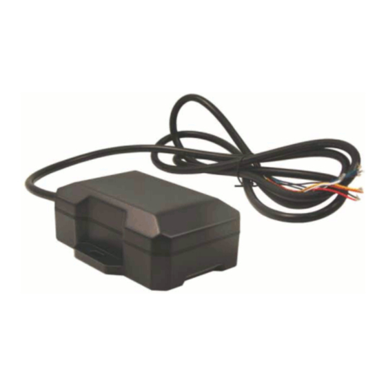
Ignition White Input IN-1 Input 1 Blue Input IN-2 Input 2 \ Rx Orange Input \ Serial Rx Out-0 Output 0 Green Output Out-1 Output 1 Brown Output Out-2 Output 2 \ Tx Yellow Output \ Serial Tx https://puls.calamp.com/wiki/TTU-12x0_Hardware_%26_Installation_Guide 8/36... -
Page 9: Serial Adapter
-160dBm Tracking Sensitivity For external models, the antenna connector is SMA female. Note that the CalAmp TTU-12x0™ requires an antenna amplifier that operates at 3VDC; 5VDC amps will not work. 3.4 External RF Connector The external antenna connection for the TTU-12x0™ is SMC with 50Ω nominal impedance. -
Page 10: Motion Sensor Input
The TTU-12x0™ has a built in high temperature threshold of 60° C. If the internal temperature of the TTU is above this value, then the input will be in the High state. If the TTU’s temperature is below this value, then the input will be in the Low state. https://puls.calamp.com/wiki/TTU-12x0_Hardware_%26_Installation_Guide 10/36... -
Page 11: Ignition And Inputs
+12v through a 10kΩ resistor) or Low (i.e. pulled to ground through a 10kΩ resistor). Input 1 is always biased low, while inputs 2-4 are biased high. The diagrams below show how to connect the inputs in both a high and low-biased configuration: https://puls.calamp.com/wiki/TTU-12x0_Hardware_%26_Installation_Guide 11/36... -
Page 12: Outputs
3.5.7 Status LEDs The TTU-12x0™ is equipped with two Status LEDs, one for GPS and one for COMM (wireless network status). The LEDs use the following blink patterns to indicate service: LED #1 (Comm LED - Orange) Definitions https://puls.calamp.com/wiki/TTU-12x0_Hardware_%26_Installation_Guide 12/36... -
Page 13: Configuration And Activation
This section details how to quickly get an TTU-12x0™ provisioned and configured to point at a specific server. It is assumed that a PEG script has already been created and is being managed through LMU Manager or PULS™, the CalAmp Maintenance System. - Page 14 ! R P , 2 3 1 9 , 0 , m y U R L . M y C o m p a n y . C o m Where myURL.MyCompany.com is the URL assigned to the server 4. Verify your settings by sending the commands: ! R P ? 2 3 1 9 , 0 ! R P ? 7 6 9 , 0 . https://puls.calamp.com/wiki/TTU-12x0_Hardware_%26_Installation_Guide 14/36...
-
Page 15: Auto Provisioning Of Gsm Or Hspa Lmus
APN 0 & 1: general.t-mobile.uk o Username: user o Password: wap TelCel Mexico (MCC 334 MNC 02) o APN 0 & 1: INTERNET.ITELCEL.COM o Username: webgprs o Password: webgprs2002 Telstra Australia (MCC 505, MNC 01, 11, 71, 72) https://puls.calamp.com/wiki/TTU-12x0_Hardware_%26_Installation_Guide 15/36... -
Page 16: Activating Gsm Or Hspa Lmu Using At Commands
4.3 Activating GSM or HSPA LMU using AT Commands Check with the CalAmp Sales team for availability of the TTU-12x0™ with GSM or HSPA modems. For a GSM/GPRS operator you will get the LMU in one of two varieties, one with a SIM and one without. -
Page 17: Accessing The Sim
Q u a l i t y o f S r v c : 1 , 0 , 0 , 3 , 0 , 0 G S M C l a s s : 4.4 Accessing the SIM https://puls.calamp.com/wiki/TTU-12x0_Hardware_%26_Installation_Guide 17/36... - Page 18 Take care not to touch the GPS Patch antenna. TTU-12x0™ SIM Alignment 4. Align the SIM so that the contacts will face into the main board and the notch is aligned to the SIM Carrier. 5. Insert the SIM. https://puls.calamp.com/wiki/TTU-12x0_Hardware_%26_Installation_Guide 18/36...
-
Page 19: Activating A Cdma Ttu-12X0
CalAmp serial number. The one the operator is interested in is the MSN-D (which they call the decimal ESN). DO NOT give them the CalAmp ESN (i.e. the top one on the label). It will only lead to the carrier telling you that the product doesn’t exist and they can’t activate it for you. -
Page 20: Activating A Cdma Ttu-12X0™ - Sprint
Wireless, it requires that the user enter several menu choices in order to complete activation. Unfortunately, this is something the TTU-12x0™ does not support, so the activation must be performed manually. Bell Mobility will provide you with a password to gain access to the network (ex: 8889). The activation procedure will be as follows: https://puls.calamp.com/wiki/TTU-12x0_Hardware_%26_Installation_Guide 20/36... - Page 21 1 2 3 4 5 6 7 8 9 0 I M S I 3 1 0 0 0 1 2 3 4 5 6 7 8 9 0 C a r r i e r C o n f i g : https://puls.calamp.com/wiki/TTU-12x0_Hardware_%26_Installation_Guide 21/36...
-
Page 22: Installing The Lmu
Whether you intend to place the LMU under a seat or into a cavity behind the vehicle’s interior molded trim, be sure the LMU will fit before drilling any holes or running cable Be certain that the cables running to the LMU will not be bent or constricted. Damage to the cables may impede https://puls.calamp.com/wiki/TTU-12x0_Hardware_%26_Installation_Guide 22/36... -
Page 23: Placement Of Antennas
(i.e. thru-hole, magnetic mount or peel and stick) and requires a ground plane to work properly. If possible, it should be located at least 3 feet from the GPS antenna. Ensure that the cable does not get crushed during installation. Please note that the antennas provided by CalAmp combine both the GPS and Comm portions. GPS Antenna Placement Guidelines In order to maximize the performance of the LMU the GPS antenna should have a clear view of the sky. -
Page 24: Access To The Sim (Subscriber Identity Module) Card
It is best not to place the LMU unit in an unusually warm location such as directly near heater vents, near hot engine components or in direct sunlight. The maximum temperature that can be tolerated by the LMU is described in the LMU Environmental Specifications section. 5.2.5 Visibility of Diagnostic LEDs https://puls.calamp.com/wiki/TTU-12x0_Hardware_%26_Installation_Guide 24/36... -
Page 25: Cable Length
LMU, you may need to read the LEDs in order to troubleshoot the problem. If you cannot fix the LMU yourself, you will need to provide the LED information to CalAmp customer support. -
Page 26: Place The Gps Antenna
Ensure that the cable is not crushed during installation or normal vehicle operation. Again, the Comm. Antenna must be located at least 20cm away from vehicle passengers, other personnel, or bystanders in order to comply with FCC radio frequency exposure limits. https://puls.calamp.com/wiki/TTU-12x0_Hardware_%26_Installation_Guide 26/36... -
Page 27: Typical Connection Sequence
In many cases it is desirable to verify that an installed TTU-12x0™ is working properly. That is, installers should verify that the GPS and communications functions of the TTU-12x0™ are working properly before departing the installation site. In https://puls.calamp.com/wiki/TTU-12x0_Hardware_%26_Installation_Guide 27/36... -
Page 28: Comm Verification
First, like the Comm Verification, there is a GPS status LED (i.e., the one closest to the SMA connector). If this LED is solid, then the LMU has found GPS service. If the LED is not visible then GPS service may be verified using an AT Command: https://puls.calamp.com/wiki/TTU-12x0_Hardware_%26_Installation_Guide 28/36... -
Page 29: Inbound Verification
2-3 minutes, installers should check antenna placement (see the Installation Notes section for placement suggestions), the antenna connector and that the antenna has a clear view of the sky. For further troubleshooting, installers should contact CalAmp Support (M2MSupport@CalAmp.com) 5.4.3 Inbound Verification The last item to verify is that the TTU-12x0™... - Page 30 This is an optional field if and is only present if the LMU has established a valid data session. This field will contain the current IP address of the LMU as assigned by the wireless network. Note that if you see a https://puls.calamp.com/wiki/TTU-12x0_Hardware_%26_Installation_Guide 30/36...
- Page 31 Direct™ server. o <inbound port>: This is the current UDP port the LMU will use to deliver its LM Direct™ data. This value should match UDP port you are using on your LM Direct™ server. It is typically 20500. https://puls.calamp.com/wiki/TTU-12x0_Hardware_%26_Installation_Guide 31/36...
-
Page 32: License Agreement
License Agreement, DO NOT INSTALL OR USE THE SOFTWARE, APIs OR DOCUMENTATION. For a full refund, return the unused media package and all accompanying materials within seven (7) days to CalAmp. Where there is no packaging or media, use of the software and/or documentation constitutes acceptance. - Page 33 Make derivative works including but not limited to translations, adaptations, arrangements or any other alteration (each of which would become the property of CalAmp or its licensors, as applicable) or make copies of the Software or Documentation except as permitted above; (2) Make copies of the Related Materials; (3) Use any CalAmp product to translate the product of another licensor unless you have the legal right to do so;...
-
Page 34: Limited Warranty
Server or at a single Site, as the case may be, accessible to the number of individual users (not concurrent users) for which the Server or Site License has been purchased as evidenced by a CalAmp License Certificate. For each Use License purchased, as evidenced by a CalAmp License Certificate, CalAmp grants the Customer the right to distribute a single Application to a single User. -
Page 35: Regulatory Information
Acknowledgement: You acknowledge that you have read this LIMITED WARRANTY, understand it and agree to be bound by its terms and conditions. You also agree that: (1) No oral or written information or advice given by CalAmp, its dealers, distributors, agents or employees shall in any way increase the scope of this Limited Warranty and you may not rely on any such information or advice;... - Page 36 TTU-12x0 Hardware & Installation Guide - PULS Wiki CalAmp DataCom Inc. certifies that it has determined that the TTU-12x0™ complies with the RF hazard requirements applicable to broadband PCS equipment operating under the authority of 47 CFR Part 24, Subpart E of the FCC Rules and Regulations.
Need help?
Do you have a question about the TTU-12 0 Series and is the answer not in the manual?
Questions and answers