Table of Contents
Advertisement
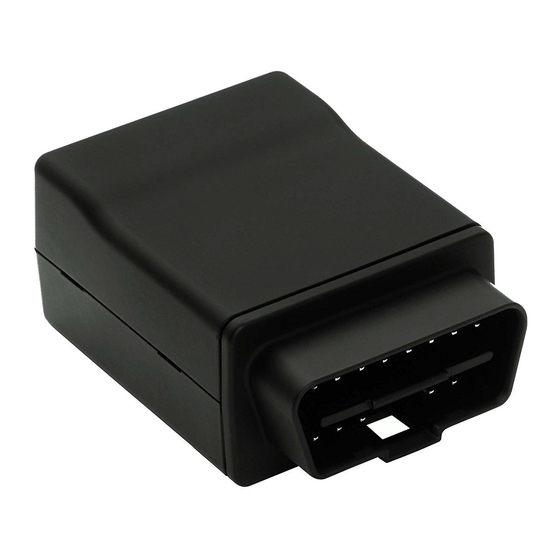
LMU-3030 Hardware & Installation Guide
Hardware and Installation
IMPORTANT: DO NOT INSTALL OR USE THE SOFTWARE OR DOCUMENTATION UNTIL YOU HAVE
READ AND AGREED TO THE
WARRANTY
AND
REGULATORY
1 Introduction
[edit][top]
Welcome to the LMU-3030™ Hardware and Installation Guide. This manual is intended to give you information
on the basic setup and installation of the CalAmp LMU-3030™ product(s) including hardware descriptions,
environmental specifications, wireless network overviews and device installation.
1.1 About This Manual
The LMU-3030™ is one of the most flexible economy mobile tracking hardware products available. In
order to accurately describe the functionality of these units we have broken this manual into the
following sections:
LMU-3030™
Guide
LICENSE AGREEMENT
INFORMATION.
AND REVIEWED
THELIMITED
Advertisement
Table of Contents

Related Manuals for CalAmp LMU-3030


Summary of Contents for CalAmp LMU-3030
- Page 1 1 Introduction [edit][top] Welcome to the LMU-3030™ Hardware and Installation Guide. This manual is intended to give you information on the basic setup and installation of the CalAmp LMU-3030™ product(s) including hardware descriptions, environmental specifications, wireless network overviews and device installation.
-
Page 2: About The Reader
System Overview – A basic description of a CalAmp LMU-3030™ based tracking system. This includes a description of roles and responsibilities of each of the CalAmp components as well as a brief overview of the wireless data technologies used by the LMU-3030™. -
Page 3: System Overview
These functions, of course, are completely dependent on the capabilities of the vehicle management application. The role of the CalAmp LMU-3030™ is to deliver the location information when and where it is needed. A typical fleet management system based on a CalAmp device includes the following components: ... -
Page 4: Component Descriptions
The Wireless Data Network provides the information bridge between the LM Direct™ server and the LMU-3030™. Wireless data networks can take a variety of forms, such as cellular networks, satellite systems or local area networks. Contact the CalAmp sales team for the networks available to the LMU- 3030™. -
Page 5: Lm Direct™ Server
2.2.2 LMU-3030™ The LMU-3030™ is responsible for delivering the location and status information when and where it is needed. Data requests mainly come from the following sources: PEG™ script within the LMU-3030™ A location or status request from the LM Direct™ server ... -
Page 6: Lmu Manager
2.2.6 LMU Manager™ LMU Manager is the primary configuration tool in the CalAmp system. It allows access to almost every feature available to the LMU-3030™. Unlike the backend software, it has the option of talking directly to an LMU-3030™... - Page 7 1 Watt. 3.1.2 Battery backup devices Please properly dispose of the battery in any of the CalAmp products that utilize one, do not just throw used batteries, replaced batteries, or units containing a back-up battery into the trash. Consult your...
-
Page 8: Environmental Specifications
To ensure proper operation in such an environment, the LMU-3030™ was subjected to standard tests defined by the Society of Automotive Engineers (SAE). The specific tests included temperature, shock, vibration, and EMI/EMC. - Page 9 850 MHz (Class 4) – 2W 900 MHz (Class 4) – 2W 1800 MHz (Class 1) – 1W 1900 MHz (Class 1) -1 W GPRS Packet Data (UDP) RoHS Compliant 3.1 LMU-3030™ connectors 3.2.1 Primary connector Connector on Vehicle side Connector on LMU-3030 side...
- Page 10 Please note that only 9 out of the 16 connector pins are actually populated on the connector. Signal Name Description Bus+ Line SAE-J1850 PWM and SAE-1850 VPW Chassis Ground Ground Signal Ground Ground Can High ISO 15765-4 and SAE-J2284 K line ISO 9141-2 and ISO 14230-4 Bus- Line SAE-J1850 PWM and SAE-1850 VPW...
- Page 11 Harness Diagrams page for more information on LMU accessories, and supported products table. 3.3 I/O Descriptions The LMU-3030™ provides the following Inputs for scripting purposes, but there are no selectable inputs on the device Digital Inputs Input 0: Ignition Sense ...
- Page 12 3.3.1 Three-Axis accelerometer input the LMU-3030™ supports an internal 3 Axis Precision Accelerometer as one of its discreet inputs. When the LMU is moved in any direction, the associated input will be in the High state. If the LMU’s accelerometer does not detect motion, then the input will be in the Low state. No external connections are required for this functionality to be operational.
-
Page 13: Configuration And Activation
Specifically, this is pointing the LMU to your LM Direct™ server, either via IP or a URL. This configuration process is accomplished via a series of AT Commands: 1. Power up the LMU-3030™ and connect a serial cable from the LMU to your laptop 2. Open a terminal session to the LMU-3030™... - Page 14 5. Enter ATIC to verify the correct settings are displayed for your Inbound Server. This configuration process is accomplished via a series of SMS Commands: 1. Power up the LMU-3030™ and your handset 2. From the handset, send an SMS message to the LMU-3030™ phone number: !RP,2319,0,ddd.ddd.ddd.ddd !RP,768,0,ddd.ddd.ddd.ddd...
- Page 15 4.2 Auto provisioning of GSM or HSPA LMUs For certain operators, the LMU can auto-populate the APN, username and password settings based on the Mobile Country Code (MCC) and the Mobile Network Code (MNC) of the SIM. Upon inserting a new SIM the APN, username and password will switch to the new SIM card's defaults if the MCC and MNC values change.
- Page 16 T-Mobile (MCC 310, MNC 16, 20, 21, 22, 23, 24, 25, 26, 27, 31, 58, 66, 80) o APN 0: INTERNET2.VOICESTREAM.COM o APN 1: INTERNET3.VOICESTREAM.COM T-Mobile UK (MCC 234, MNC 30,31,32) o APN 0 & 1: general.t-mobile.uk o Username: user o Password: wap TelCel Mexico (MCC 334 MNC 02) o APN 0 &...
- Page 17 4.3 Activating GSM or HSPA LMU using AT Commands Check with the CalAmp Sales team for availability of the LMU-3030™ with GSM or HSPA modems. For a GSM/GPRS operator you will get the LMU in one of two varieties, one with a SIM and one without.
- Page 18 The last item an operator may provide is a SIM PIN. The PIN is effectively a password to the device. The main difference here is that the PIN will restrict all the capabilities of the GSM device, where the SPC is used just for configuration. The activation sequence for a GSM LMU would therefore look as follows: AT$APP PARAM 2306,0,“myAPN.myOperator.com”...
-
Page 19: Phone Number
VBus header and pull up then repeat this action near the SIM cover. Remove the top-plate to expose the top-side of the LMU-3030™’s main-board. Align the SIM so the contacts are facing up and the notch is facing into the LMU-3030™ Inserst the SIM card into the LMU... - Page 20 The ESN on the LMU is the CalAmp serial number. The one the operator is interested in is the MSN-D (which they call the decimal ESN). DO NOT give them the CalAmp ESN (i.e. the top one on the label). It will only lead to the carrier telling you that the product doesn’t exist and they can’t activate it for you.
- Page 21 1. Power on the LMU-3030™, making sure you can observe the behavior of the Comm LED. 2. Wait until the Comm LED turns solid. This could take up to 5 minutes. 3. If after 5 minutes you observe that the Comm LED transitions from a slow blink to a fast blink several times (i.e.
- Page 22 Activating an LMU-3030™ on the Sprint CDMA network is identical to activating on the Verizon network. 1. Power on the LMU-3030™, making sure you can observe the behavior of the Comm LED. 2. Wait until the Comm LED turns solid. This could take up to 5 minutes.
-
Page 23: Preventing Accidental Or Unauthorized Modification
3. Leave the unit plugged in with vehicle ignition on until the detection process has completed. Vehicle detection status can be checked through SMS over the air or with AT Commands using the CalAmp serial connection cable. The AT Command to check vehicle detection status. -
Page 24: Installation Verification
4. Once the vehicle detection has completed the vehicle ignition can then be turned off. 5.3 Installation Verification In many cases it is desirable to verify that an installed LMU-3030™ is working properly. That is, installers should verify that the GPS and communications functions of the LMU-3030™ are working properly before departing the installation site. - Page 25 If any of the responses return Not-Acquired or Not-Registered (and the APN is correct), the wireless network operator should be contacted for further troubleshooting. Please note that it may take several seconds (or longer) for the LMU-3030™ to communicate with the modem and acquire the wireless network.
- Page 26 5.3.3 Inbound Verification The last item to verify is that the LMU-3030™ is sending data to the correct server. In general, this is a two-step process that will need the aid of an observer on the back end. That is, a technician will have to be logged in so they can monitor data coming into the backend mapping/vehicle management application.
-
Page 27: Verification Via Sms
(ddd.ddd.ddd.ddd) and port (<ppppp>) are correct. The second step is to verify that the LMU-3030™ is sending data. The best way to do this is to force the LMU-3030™ to send in an unacknowledged Event Report (i.e., its current GPS location) with the... - Page 28 o <Firmware Version>: The current firmware version in use by the LMU COM: o <RSSI>: This is the signal strength the wireless modem sees from the network. In general the LMU is at least scanning for the network if the RSSI is not -113. o [./d/D]: If the character ‘D’...
- Page 29 This field, if present, indicates a problem with the LMU’s GPS antenna. A value of Short indicates that the antenna cable has likely been crushed. A value of Open indicates that the antenna cable is either cut or disconnected. A value of Off indicates that the LMU’ GPS receiver is off. - [No Time Sync]: If this field is present, it indicates that the LMU’s GPS receiver has not been able to find even a single GPS satellite.
-
Page 30: License Agreement
This is a legal agreement between you, the Customer, and CalAmp DataCom Incorporated (“CalAmp”). By installing and/or using the software or documentation, you are consenting to the terms of this License. If you do not agree to the terms of this non-exclusive License Agreement, DO NOT INSTALL OR USE THE SOFTWARE, APIs OR DOCUMENTATION. - Page 31 CalAmp, or which you have received or downloaded electronically. “Application” means a compiled or executable software program created by Developer that uses some or all of the functionality of the Software. “Software Copies”...
- Page 32 All rights not specifically granted in this License are reserved by CalAmp. Customer agrees to include the notice “Copyright © 1999 – 2009 CalAmp DataCom Inc., All Rights Reserved” in Applications developed with the Software. Customer agrees to include the following CalAmp Copyright and Government Restricted Use notice in all documentation and in any Application on-line help or readme file.
- Page 33 Software or Documentation except as permitted above; (2) Make copies of the Related Materials; (3) Use any CalAmp product to translate the product of another licensor unless you have the legal right to do so; (4) Allow a greater number of Developers to access the Software at any one time than the total number of Developer licenses for which you have paid;...
-
Page 34: Limited Warranty
(5%) between the number of Use Licenses granted and the number paid for, Customer shall pay all costs related to performing the audit in addition to remitting payment for those licenses granted in excess of those paid for as evidenced by a CalAmp License Certificate. - Page 35 CalAmp DataCom Inc., 1401 North Rice Ave. Oxnard, CA 93030. Disclaimer Regarding the Software, Documentations and Related Materials: THE SOFTWARE, DOCUMENTATION AND RELATED MATERIALS ARE PROVIDED “AS IS.” EXCEPT AS MAY...
-
Page 36: Regulatory Information
(PCS) equipment is subject to the radio frequency radiation exposure requirements specified in § 1.1307(b), § 2.1091 and § 2.1093, as appropriate. CalAmp DataCom Inc. certifies that it has determined that the LMU-3030™ complies with the RF hazard requirements applicable to broadband PCS equipment operating under the authority of 47 CFR Part 24, Subpart E of the FCC Rules and Regulations. - Page 37 20 cm is normally maintained between the transmitter’s antenna and the body of the user or nearby persons. The LMU-3030™ is not designed for or intended to be used in mobile applications (within 20 cm of the body of the user) and such uses are strictly prohibited.
- Page 38 —Increase the separation between the equipment and receiver. —Connect the equipment into an outlet on a circuit different from that to which the receiver is connected. —Consult the dealer or an experienced radio/TV technician for help. This device complies with Industry Canada license-exempt RSS standard(s). Operation is subject to the following two conditions: (1) this device may not cause interference, and (2) this device must accept any interference, including interference that may cause undesired operation of the device.
Need help?
Do you have a question about the LMU-3030 and is the answer not in the manual?
Questions and answers