Advertisement
Quick Links
Hardware and Installation
IMPORTANT: DO NOT INSTALL OR USE THE SOFTWARE OR DOCUMENTATION
UNTIL YOU HAVE READ AND AGREED TO THE
REVIEWED THE
[edit][top] 1 Introduction
Welcome to the TTU-2820™ Hardware and Installation Guide. This manual is intended to give
you information on the basic setup and installation of the CalAmp TTU-2820™ product(s)
including hardware descriptions, environmental specifications, wireless network overviews and
device installation.
[edit][top] 1.1 About This Manual
The TTU-2820™ is one of the most flexible economy mobile tracking hardware products
available. In order to accurately describe the functionality of these units we have broken
this manual into the following sections:
System Overview – A basic description of a CalAmp TTU-2820™ based
tracking system. This includes a description of roles and responsibilities of each
of the CalAmp components as well as a brief overview of the wireless data
technologies used by the TTU-2820™.
TTU-2820™
Guide
LIMITED WARRANTY
LICENSE AGREEMENT
AND
REGULATORY
AND
INFORMATION.
Advertisement

Related Manuals for CalAmp TTU-2820


Summary of Contents for CalAmp TTU-2820
- Page 1 INFORMATION. [edit][top] 1 Introduction Welcome to the TTU-2820™ Hardware and Installation Guide. This manual is intended to give you information on the basic setup and installation of the CalAmp TTU-2820™ product(s) including hardware descriptions, environmental specifications, wireless network overviews and device installation.
- Page 2 TTU-2820™. Installation and Verification – Provides guidance for the installation of the TTU-2820™ in a vehicle and instructions on how to verify the installation is performing adequately. [edit][top] 1.2 About The Reader In order to limit the size and scope of this manual, the following assumptions have been made about the reader.
- Page 3 These functions, of course, are completely dependent on the capabilities of the vehicle management application. The role of the CalAmp TTU-2820™ is to deliver the location information when and where it is needed.
- Page 4 [edit][top] 2.2.1 Wireless Data Network The Wireless Data Network provides the information bridge between the LM Direct™ server and the TTU-2820™. Wireless data networks can take a variety of forms, such as cellular networks, satellite systems or local area networks. Contact the CalAmp sales team for the networks available to the TTU-2820™.
- Page 5 Such examples could include instant messaging between vehicles or a central office, in-vehicle mapping or driving directions, email or database access. In most of these cases you will be using the TTU-2820™ as a wireless modem as well as a vehicle-location device.
- Page 6 LMU Manager is the primary configuration tool in the CalAmp system. It allows access to almost every feature available to the TTU-2820™. Unlike the backend software, it has the option of talking directly to an TTU-2820™ or making a request forwarded by the LM Direct™ server.
- Page 7 One potential source of EOS is proximity of one TTU-2820™ GPS Antenna to another TTU-2820™ GSM Antenna. Should one of the units be in a transmit mode the potential exists for the other unit to become damaged. Therefore any TTU-2820™ GPS Antenna should be kept at least four inches apart from any active TTU-2820™...
- Page 8 To ensure proper operation in such an environment, the TTU-2820™ was subjected to standard tests defined by the Society of Automotive Engineers (SAE). The specific tests included temperature, shock, vibration, and EMI/EMC.
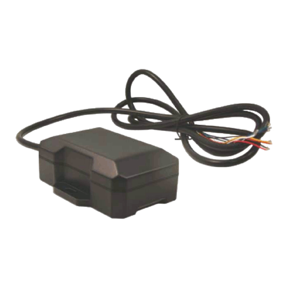
- Page 9 850/900/1800/1900 quad-band GPRS class 12, EDGE MCS1-MCS9 RoHS Compliant [edit][top] 3.2 TTU-2820™ Connectors [edit][top] 3.2.1 Primary Connector The TTU-2820™ uses 12 22AWG leads for its power and I/O connections. These leads are mapped as follows: Signal Input or Wire Description...
- Page 10 Input TTU-2820™ Power and I/O leads [edit][top] 3.2.2 Serial Adapter To add a host serial adapter to the TTU-2820™ there is 1 additional part: Part Number 134074: Serial Adapter. To use this part, simply connect the following wires together on the screw block - red to red, black to black, orange to blue/black and yellow to green/black.
- Page 11 The TTU-2820™’s GPS receiver has the following specifications: 50 channel GPS receiver Accuracy: 2.5 meter CEP (with SA off) -162dBm Tracking Sensitivity [edit][top] 3.4 I/O Descriptions The TTU-2820™ provides the following I/O: Digital Inputs Input 0: Ignition Sense (Always biased low) ...
- Page 12 [edit][top] 3.4.2 Power State Input The TTU-2820™ can detect if it’s using external power or if it’s using its internal back- up battering. If the TTU-2820™ is using external power, this input will be in the Low state.
- Page 13 The ignition input is pulled to ground through the 10k resistance, where the other inputs can either be normally High (i.e. pulled to +12v through a 10kΩ resistor) or Low (i.e. pulled to ground through a 10kΩ resistor). Input 1 is always biased low, while inputs 2-4 are biased high.
- Page 15 If this output is cleared, the TTU will use the external power supply. By default, this output is cleared so the TTU-2820™ will operate off external power. Enable / Disable Battery Charging This output allows the TTU to enable or disable the charging of its internal battery.
- Page 16 [edit][top] 3.4.7 Status LEDs The TTU-2820™ is equipped with two Status LEDs, one for GPS and one for COMM (wireless network status). The LEDs use the following blink patterns to indicate service: LED #1 (Comm LED - Orange) Definitions Condition...
Need help?
Do you have a question about the TTU-2820 and is the answer not in the manual?
Questions and answers