Table of Contents

Related Manuals for CalAmp TTU-4531


Summary of Contents for CalAmp TTU-4531
- Page 1 TTU-4530™ TTU-4531™ Hardware and Installation Guide IMPORTANT: DO NOT INSTALL OR USE THE SOFTWARE OR DOCUMENTATION UNTIL YOU HAVE READ AND AGREED TO THE LICENSE AGREEMENT AND REVIEWED THELIMITED WARRANTY REGULATORY INFORMATION.
-
Page 2: About This Manual
System Overview – A basic description of a CalAmp TTU-4530™ based tracking system. This includes a description of roles and responsibilities of each of the CalAmp components as well as a brief overview of the wireless data technologies used by the TTU-4530™. -
Page 3: System Overview
1.4 About the CalAmp Trailer Tracking Unit-TTU-4530™ The CalAmp Trailer Tracking Unit-4530™ (TTU-4530™) is a mobile device that resides in private, commercial or government vehicles. The TTU-4530™ is a single box enclosure incorporating a processor, a GPS receiver, a wireless data modem, and a vehicle-rated power supply. The TTU- 4530™... - Page 4 These functions, of course, are completely dependent on the capabilities of the vehicle management application. The role of the CalAmp TTU-4530™ is to deliver the location information when and where it is needed. A typical fleet management system based on a CalAmp device includes the following components: ...
-
Page 5: Component Descriptions
The Wireless Data Network provides the information bridge between the LM Direct™ server and the TTU-4530™. Wireless data networks can take a variety of forms, such as cellular networks, satellite systems or local area networks. Contact the CalAmp sales team for the networks available to the TTU- 4530™. -
Page 6: Hardware Overview
Handling Precautions 3.1.2 Battery Back-up devices Please properly dispose of the battery in any of the CalAmp products that utilize one, do not just throw used batteries, replaced batteries, or units containing a back-up battery into the trash. Consult your local waste management facility for proper disposal instructions. - Page 7 The TTU-4530™ is designed to operate in environments typically encountered by fleet vehicles, including wide temperature extremes, voltage transients, and potential interference from other vehicle equipment. To ensure proper operation in such an environment, the TTU-4530™ was subjected to standard tests defined by the Society of Automotive Engineers (SAE).
-
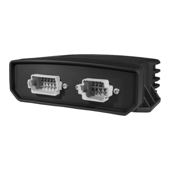
Page 8: Serial Interface Connectors
EMC compliant for a ground vehicle environment SAE Test: SAE J1113 Parts 2, 12, 21 and 41 Operating Voltage Range The TTU-4530™ supports vehicles with 12 or 24 VDC systems including transients and electrical system noise; this includes ranges from 7 to 32 VDC. Electrostatic Discharge (ESD) No damage or performance degradation after the ESD disturbance. - Page 9 To serially connect to Aux1, simply connect the following wires together from the power harness to the screw terminal block - red to red, black to black, yellow to green/brown and orange to blue/brown. Make sure to do a continuity check to determine pin configurations(There are multiple black wires and thus this step is necessary to ensure that you are using the correct ground outlet) ...
- Page 10 Input-3 In-3 sel Input-4 In-4 sel Input-5 In-5 sel Input-6 In-6 sel Input-7 In-7 sel Input-8 Motion Input-9 VBUS Active Input-10 Pwr State Input-11 Vbatt Low Input-12 1BB Detect Input-13 Batt Virt Ign Input-14 Pure Virt Ign Input-15 Radio Active Wakeup Output-0 Output-1 Out-1...
-
Page 11: Status Leds
Sleep Processor STM32F205 App ID 321-HSPAg6 3.4.1 3-Axis Accelerometer Input The TTU-4530™ supports an internal 3 Axis Precision Accelerometer as one of its discreet inputs. When the TTU is moved in any direction, the associated input will be in the High state. If the TTU’s accelerometer does not detect motion, then the input will be in the Low state. -
Page 12: Configuration And Activation
TTU-4530™. (See LM Direct™ Reference Guide for details) You are using the standard wiring harness from CalAmp and the serial port expansion harness. You have created a HyperTerminal or Putty session. You have contacted the CalAmp sales team regarding the network availability of the TTU- 4530™. - Page 13 AT$APP PARAM 2319,0,ddd.ddd.ddd.ddd AT$APP PARAM 768,0,ddd.ddd.ddd.ddd (32-bit products only) AT$APP PARAM 769,0,ppppp Where ddd.ddd.ddd.ddd is the publicly addressable IPV4 address of your LM Direct™ server and ppppp is the UDP port number. 4. Alternatively if a URL has been set up for your LM Direct™ server, the TTU may be programmed with: AT$APP PARAM 2319,0,myURL.MyCompany.Com Where myURL.MyCompany.com is the URL assigned to the server.
- Page 14 !RP?769,0 .2 Auto provisioning of GSM or HSPA TTUs For certain operators, the TTU can auto-populate the APN, username and password settings based on the Mobile Country Code (MCC) and the Mobile Network Code (MNC) of the SIM. Upon inserting a new SIM the APN, username and password will switch to the new SIM card's defaults if the MCC and MNC values change.
- Page 15 o Password: pass T-Mobile (MCC 310, MNC 16, 20, 21, 22, 23, 24, 25, 26, 27, 31, 58, 66, 80) o APN 0: INTERNET2.VOICESTREAM.COM o APN 1: INTERNET3.VOICESTREAM.COM T-Mobile UK (MCC 234, MNC 30,31,32) o APN 0 & 1: general.t-mobile.uk o Username: user o Password: wap TelCel Mexico (MCC 334 MNC 02)
- Page 16 4.3 Activating GSM or HSPA TTU using AT Commands Check with the CalAmp Sales team for availability of the TTU-4530™ with GSM or HSPA modems. For a GSM/GPRS operator you will get the TTU in one of two varieties, one with a SIM and one without.
-
Page 17: Phone Number
The activation sequence for a GSM TTU would therefore look as follows: AT$APP PARAM 2306,0,“myAPN.myOperator.com” AT$APP PARAM 2306,1,“myAPN.myOperator.com” AT$APP PARAM 2314,0,“myUSername” AT$APP PARAM 2315,0,“myPassword” For a blank APN the following command can be used: AT$APP PARAM 2306,0,“” (for a blank APN) Only enter this next command if you have been given a non-zero PIN as any errors may lock you out of the modem. - Page 18 GPRS APN: IP:Public Quality of Srvc: 1,0,0,3,0,0 GSM Class: The SIM carrier is located inside the TTU-4530™ housing on the back center of the device. Top View: Bottom View:...
- Page 19 The ESN on the TTU is the CalAmp serial number. The one the operator is interested in is the MSN-D (which they call the decimal ESN). DO NOT give them the CalAmp ESN (i.e. the top one on the label). It will only lead to the carrier telling you that the product doesn’t exist and they can’t activate it for you.
- Page 20 Channel: Band:Side: 800:B Base Station ID: Network ID: System ID: ESN (Modem S/N: 2676319948 [9F8566CC] Phone Number: 1234567890 IMSI: 310001234567890 CarrierConfig: Note that the Phone Number should match the MDN value the carrier gave you. The last 10 digits of the IMSI field should match the MIN/MSID value they gave you.
-
Page 21: Preparing For Installation
Once configured, you may verify that the TTU-4530’s™ modem has registered to the CDMA network. Enter: AT$APP COMM STATUS? The response should be similar to: CDMA Service: IS-2000 Connection: RSSI: -80 dBm Channel: Band:Side: 800:B Base Station ID: Network ID: System ID: 4145 ESN (Modem S/N:... -
Page 22: Plan The Installation
Input and output cables Relays TTU peripherals (i.e. Serial adapter, jPOD, TetheredLocator) Host serial devices (e.g. PDAs, laptops, other serial devices) 5.2 Plan The Installation Verify Power, Ground and Ignition. Be sure to check each source (power, ground and ignition) to ensure that the proper signaling exists. -
Page 23: Placement Of Antennas
If possible, it should be located at least 3 feet from the GPS antenna. Ensure that the cable does not get crushed during installation. Please note that the antennas provided by CalAmp combine both the GPS and Comm portions. - Page 24 GPS Antenna Placement Guidelines In order to maximize the performance of the TTU the GPS antenna should have a clear view of the sky. When installing the GPS antenna on a vehicle, make sure that there are no obstructions close to the antenna that might block the view 360°...
-
Page 25: Access To The Sim (Subscriber Identity Module) Card
horizon with the best location being near the center of the roof. For more covert installs, directly under the front or rear-windshields are also acceptable. Examples of Good (Green), OK(Yellow) and Poor(Red) combo antenna placements Examples OK(Yellow) and Poor(Red) internal antenna placements 5.2.3 Access to the SIM (Subscriber Identity Module) Card When used in a GSM or iDEN network, each TTU uses a Subscriber Identity Module (SIM) card, which should be inserted before you install the TTU for the first time. - Page 26 If at any time you should encounter a problem with the TTU, you may need to read the LEDs in order to troubleshoot the problem. If you cannot fix the TTU yourself, you will need to provide the LED information to CalAmp customer support. For information about how to interpret the LEDs, see the Status LED Behavior section.
-
Page 27: Connect Power, Ignition, And Ground
Attach the TTU to the solid body of the vehicle, not to plastic panels. The TTU can be placed out of sight by removing interior trim and molding to expose available space, then replacing the trim once the TTU is in place 5.3.2 Connect power, ignition, and ground. -
Page 28: Mount The Comm. Antenna
GPS Antenna Location 5.3.4 Mount the Comm. Antenna. When using separate Comm and GPS antennas, it is best to locate the Comm. Antenna at least 3 feet from the GPS antenna. Ensure that the cable is not crushed during installation or normal vehicle operation. -
Page 29: Installation Verification
Connect any peripherals to the TTU Plug in the power harness. The physical installation of the TTU hardware is now complete. Completed Install – separate antennas Completed Install - Internal antennas 5.4 Installation Verification In many cases it is desirable to verify that an installed TTU-4530™ is working properly. That is, installers should verify that the GPS and communications functions of the TTU-4530™... - Page 30 5.4.1 Comm Verification Installers should first verify that the TTU-4530™ has been acquired and has registered to the wireless network. This may be verified in one of two ways. First, installers may look at the Comm LED (i.e., the one closest to the SMC antenna connector). If this LED is solid, then the TTU has registered to the network and established a data session.
- Page 31 (see the Installation Notes section for placement suggestions), the antenna connector and that the antenna has a clear view of the sky. For further troubleshooting, installers should contact CalAmp Support (M2MSupport@CalAmp.com) 5.4.3 Inbound Verification The last item to verify is that the TTU-4530™ is sending data to the correct server. In general, this is a two-step process that will need the aid of an observer on the back end.
- Page 32 INBOUND 0 ADDR ddd.ddd.ddd.ddd:ppppp * INBOUND 0 URL myURL.myCompany.com INBOUND 1 ADDR 0.0.0.0:20500 INBOUND 1 URL INBOUND 2 ADDR 0.0.0.0:20500 INBOUND 3 ADDR 0.0.0.0:20500 The installer will need to verify with a backend technician that the, URL (myURL.myCompany.com ), IP address (ddd.ddd.ddd.ddd) and port (<ppppp>) are correct.
- Page 33 INB:<inbound IP address>:<inbound port> <Inbound Protocol (LMD/LMX)> APP: o <App ID>: The Application ID value of the TTU indicating the host platform and the wireless networking technology of the TTU. o <Firmware Version>: The current firmware version in use by the TTU COM: o <RSSI>: This is the signal strength the wireless modem sees from the network.
- Page 34 o [<APN>] The current Access Point Name in use by a GSM TTU. GPS: o [Antenna <Short/Open/Off>]: This field, if present, indicates a problem with the TTU’s GPS antenna. A value of Short indicates that the antenna cable has likely been crushed. A value of Open indicates that the antenna cable is either cut or disconnected.
- Page 35 This is a legal agreement between you, the Customer, and CalAmp DataCom Incorporated (“CalAmp”). By installing and/or using the software or documentation, you are consenting to the terms of this License. If you do not agree to the terms of this non-exclusive License Agreement, DO NOT INSTALL OR USE THE SOFTWARE, APIs OR DOCUMENTATION.
- Page 36 CalAmp, or which you have received or downloaded electronically. “Application” means a compiled or executable software program created by Developer that uses some or all of the functionality of the Software.
- Page 37 All rights not specifically granted in this License are reserved by CalAmp. Customer agrees to include the notice “Copyright © 1999 – 2009 CalAmp DataCom Inc., All Rights Reserved” in Applications developed with the Software. Customer agrees to include the following CalAmp Copyright and Government Restricted Use notice in all documentation and in any Application on-line help or readme file.
- Page 38 Software or Documentation except as permitted above; (2) Make copies of the Related Materials; (3) Use any CalAmp product to translate the product of another licensor unless you have the legal right to do so; (4) Allow a greater number of Developers to access the Software at any one time than the total number of Developer licenses for which you have paid;...
- Page 39 (5%) between the number of Use Licenses granted and the number paid for, Customer shall pay all costs related to performing the audit in addition to remitting payment for those licenses granted in excess of those paid for as evidenced by a CalAmp License Certificate.
- Page 40 CalAmp DataCom Inc., 1401 North Rice Ave. Oxnard, CA 93030. Disclaimer Regarding the Software, Documentations and Related Materials: THE SOFTWARE, DOCUMENTATION AND RELATED MATERIALS ARE PROVIDED “AS IS.” EXCEPT AS MAY...
- Page 41 (PCS) equipment is subject to the radio frequency radiation exposure requirements specified in § 1.1307(b), § 2.1091 and § 2.1093, as appropriate. CalAmp DataCom Inc. certifies that it has determined that the TTU-4530™ complies with the RF hazard requirements applicable to broadband PCS equipment operating under the authority of 47 CFR Part 24, Subpart E of the FCC Rules and Regulations.
- Page 42 Warning (Part 15.21) Changes or modifications not expressly approved by Calamp Wireless Networks could void the user’s authority to operate the equipment. Manufacturer is not responsible for any radio or TV interference caused by unauthorized modifications to this equipment.
- Page 43 Le présent appareil est conforme aux CNR d'Industrie Canada applicables aux appareils radio exempts de licence. L'exploitation est autorisée aux deux conditions suivantes : (1) l'appareil ne doit pas produire de brouillage, et (2) l'utilisateur de l'appareil doit accepter tout brouillage radioélectrique subi, même si le brouillage est susceptible d'en compromettre le fonctionnement.
Need help?
Do you have a question about the TTU-4531 and is the answer not in the manual?
Questions and answers