
Subscribe to Our Youtube Channel
Related Manuals for RAIS Viva 100 L Gas


Summary of Contents for RAIS Viva 100 L Gas
- Page 1 POSITIV Installation & Operation Manual RAIS VIVA L Direct Vent Gas Stove OUTLINE NEGATIV USA / Canada...
-
Page 2: Revision : Date
English RAIS - User manual for VIVA L Gas FIRE OR EXPLOSION HAZARD Failure to follow safety warnings exactly could result in serious injury, death, or pro- perty damage. -Do not store or use gasoline or other flammable vapors and liquids in the vicinity of this or any other appliance. - Page 3 English RAIS - User manual for VIVA L Gas Assurez-vous de bien suivre les instructions données dans cette notice pour réduire au minimum le risque d’incindie ou d’explosion ou pour éviter tout dommage matériel, toute blessure ou la mort. Ne pas entreposer ni utilizer d’essence ni d’autres vapeurs ou liquides inflam- mables dans le voisinage de cet appareil ou de tout autre appareil.
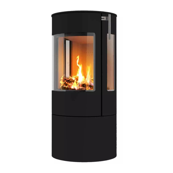
- Page 4 English RAIS - User manual for VIVA L Gas This manual covers the following models: Viva 100 L Gas – without side glass Viva 100 LG Gas – with side glass Viva 100 L Classic Gas – without side glass Viva 100 LG Classic Gas –...
-
Page 5: Table Of Contents
IT CAN BE FOUND IN THE BACK OF THE MANUAL WE STRONGLY SUGGEST THAT YOU READ THIS MANUAL THO- ROUGHLY BEFORE BE- GININNG THE INSTALLATION OF THE RAIS GAS STOVE. ALTHOUGH THE BASIC REQUIREMENTS FOR THE INSTALLATION OF ALL DIRECT VENT GAS HEATERS ARE SIMILAR,... -
Page 6: Important Safety Information
English RAIS - User manual for VIVA L Gas IMPORTANT SAFETY INFORMATION THE INSTALLATION MUST CONFORM WITH LOCAL CODES OR, IN THE ABSENCE OF LOCAL CODES, WITH THE NATIONAL FUEL GAS CODE, ANSI Z223.1 OR THE CANADIAN INSTALLATION CODE, CAN/CGA B149. - Page 7 English RAIS - User manual for VIVA L Gas CHILDREN AND ADULTS SHOULD BE ALERTED TO THE HAZARDS OF HIGH SURFACE TEMPERATURES AND SHOULD STAY AWAY TO AVOID BURNS OR CLOTHING IGNITI- YOUNG CHILDREN SHOULD BE CAREFULLY SUPERVISED WHEN THEY ARE IN THE SAME ROOM AS THE APPLIANCE.
- Page 8 English RAIS - User manual for VIVA L Gas NE PAS SE SERVER DE CET APPAREIL S’IL A ÉTÉ PLUNGE DANS L’EAU, MÊME PARTI- ELLEMENT. FAIRE INSPECTER L’APPAREIL PAR UN TECHNICIAN QUALIFIÉ ET REMPLA- CER TOUTE PARTIE DU SYSTÈME DE CONTRÔLE ET TOUTE COMMANDE QUI ONT ÉTÉ...
-
Page 9: General Comments
Do not use the stove if the door gasket is broken or worn. This stove is designed for use in many different installation situations, which can be seen in this manual. Only chimneys approved by RAIS may be used with this product. (see chimney section) This stove is intended for chimneys with balanced draughts (Air intake and draught in same chimney) so there is no need for any extra air supply for combustion. -
Page 10: Introduction
Introduction congratulations with your new RAIS Product. A RAIS stove is more than just a source of heat, it also expresses how you put the em- phasis on good design and high quality in your home. In order get the most pleasure and benefit from your new stove, it is important that you read the manual thoroughly before it is installed and put to use. -
Page 11: Guarantee
RAIS - User manual for VIVA L Gas Guarantee RAIS stoves are checked several times with regard to safety, as well as the quality of materials and manufacturing. We offer a guarantee on all models and the guarantee commences on the date of installation. -
Page 12: Specifications
English RAIS - User manual for VIVA L Gas SPECIFICATIONS INPUT Natural Gas Propane (LP) Input Rating-Btu/hr 31,000 25,600 Min. Input-Btu/hr 8,000 8,000 Orifice-Marking (Front) Orifice-Marking (Rear) 260 (x2) 100 (x2) GAS SUPPLY Manifold Pressure 4.0”w.c. / 1.0kPa 10.8”w.c. / 2.7kPa Min. -
Page 13: Installation
English RAIS - User manual for VIVA L Gas INSTALLATION Several issues must be addressed when selecting a suitable location for your VIVA L. The minimum clear- ances to combustible construction are listed below. In addition, ac- cess to the gas supply must be considered. The location of the stove will also affect the... - Page 14 English RAIS - User manual for VIVA L Gas MINIMUM CLEARANCES TO COMBUSTIBLE CONSTRUCTION Stove to Left Side Wall 6” (150mm) Stove to Corner Wall 2” (51mm) Stove to Right Side Wall 6” (150mm) Stove to Ceiling 35” (890mm) Stove to Rear Wall 2”...
-
Page 15: Massachusetts Requirements
English RAIS - User manual for VIVA L Gas MASSACHUSETTS REQUIREMENTS The gas stove is shipped with a 3/8” NPT female connection. The gas supply piping should have a separate gas shutoff valve and a 1/8” NPT plugged tapping upstream of the valve. The stove and its main control valve must be disconnected from the gas supply piping system during any pressure testing of that system at test pressures in excess of 1/2 psi (3.5 kPa). -
Page 16: Venting
English RAIS - User manual for VIVA L Gas VENTING The VIVA L Gas Stove has been tested and listed for installation with 4” X 6 5/8” Simpson DuraVent GS®, AmeriVent Direct® , Selkirk DT® , BDM Pro-Form DVS®, ICC EXCEL Direct® and OLYMPIA CHIMNEY SUPPLY Ventis® direct vent- ing components. - Page 17 English RAIS - User manual for VIVA L Gas Horizontal Wall Vent Termination Flue sizing: VIVA L : Ø4”x6 5/8”⅝ Connector on Appliance. Ø4”x6 5/8”⅝Maybe used Throughout, Alternatively, Ø5”x8” Expander may be used, so that Ø5”x8” flue can be used thereafter.
- Page 18 English RAIS - User manual for VIVA L Gas Minimum Vertical Flue Height: 2 feet (600mm) Flue Restrictors to be fitted, Ø 4”x6 5/8”⅝: Vertical Rise < 3 feet (1m) No Restrictor Vertical Rise 3 – 8 feet (1-2m) Ø62mm Restrictor Vertical Rise >...
- Page 19 English RAIS - User manual for VIVA L Gas Vertical Roof Termination...
- Page 20 English RAIS - User manual for VIVA L Gas Vertical Roof Termination on angle...
- Page 21 English RAIS - User manual for VIVA L Gas Vertical Roof Termination with bends...
- Page 22 English RAIS - User manual for VIVA L Gas PLEASE NOTE: If your specific venting configuration is over 15 feet (4.5m), you must use one of the approved direct vent venting systems that utilizes a stainless steel inner liner. This requirement is part of the ANSI standards and is based on testing conducted to determine where the exhaust gas temperature drops to the point where condensa- tion might occur in the vent pipe.
- Page 23 English RAIS - User manual for VIVA L Gas VENT TERMINAL CLEARANCES (Refer to illustration on page 15) Canadian installations U.S. installations A = Clearance above grade, verranda, 12 inches (30 cm) 12 inches (30 cm) porch, deck or balcony...
-
Page 24: Gas Connection
English RAIS - User manual for VIVA L Gas GAS CONNECTION The gas supply piping should have a separate gas shut-off valve and a 1/8” NPT plugged tapping upstream of the valve. The VIVA L and its inlet regulator and main burner valve must be disconnected from the gas supply piping system during any pressure testing of that system at test pressures in excess of 1/2 psi (3.5kPa). -
Page 25: Changes To Chimney Connection
English RAIS - User manual for VIVA L Gas Cold Climate Insulation For cold climate installations, seal all cracks around your appliance with noncombus- tible material and wherever cold air could enter the room. It is especially important to insulate outside chase cavity between studs and under floor on which appliance rests, if floor is above ground level. - Page 26 English RAIS - User manual for VIVA L Gas 2. Loosen the three screws on the outer flange on the top sur- face of the stove. And remove it. 3. Loosen the three screws on the inner flange on the bottom surface of the stove.
- Page 27 English RAIS - User manual for VIVA L Gas 7. If the ceramic logs are fitted remove these. 8. The thin side pieces of the back plate are removed by loosening the two screws, one at the top and one at the bottom. The side pieces can then be removed.
-
Page 28: Conversion To Bottled Gas (Lpg)
English RAIS - User manual for VIVA L Gas Conversion to bottled gas (LPG) The stove is supplied configured for natural gas but can be converted to bottled gas (LPG). The conversion must only be carried out by an author- ised gas engineer. - Page 29 English RAIS - User manual for VIVA L Gas The nozzle for the main burner for LPG is marked "80" The nozzle for the main burner for natu- ral gas is marked "120" The nozzle for the pilot light for LPG is marked "27.1"...
- Page 30 English RAIS - User manual for VIVA L Gas The gas unit needs to be dismantled to gain access to the nozzles. Do this in the following manner: Lift the perforated plate up and out of the stove. Loosen the four screws holding the...
- Page 31 English RAIS - User manual for VIVA L Gas Now the gas unit can be lifted out carefully by tilting and rotating the unit a little. Once the gas unit has been dismounted, replace the four nozzles and adjust the three air intakes.
- Page 32 English RAIS - User manual for VIVA L Gas Remove the nozzle for the main burner by loosening the coupling and carefully pulling the pipe out and then unscrewing the noz- zle. Fit the LPG nozzle and tighten the lock nut.
- Page 33 English RAIS - User manual for VIVA L Gas The air intake to the main burner is adjust- ed for LPG configuration by loosening the two nuts and pushing the plate all the way towards the burner. (The hole fully open)
- Page 34 English RAIS - User manual for VIVA L Gas The air intakes need to be reversed therefore when the stove is config- ured for LPG. The gas unit is reassembled using the four screws. Replace the perforated plate and fully assemble the stove.
- Page 35 English RAIS - User manual for VIVA L Gas Fitting of Secondary burners The burners are inserted above the pipes sticking through the perforated plate. Note that there is a right burner and a left one so it is important that they are posi- tioned as shown, i.e., that the...
-
Page 36: Arrangement Of Embers And Ceramic Logs
English RAIS - User manual for VIVA L Gas Arrangement of "Embers" and ”Logs" When layers of embers and the ceramic logs are arranged in the com- bustion chamber, it is important that the pilot flame and its thermosen- sor are not covered over. And that no glowing material finds its way down under the pilot plate guard. - Page 37 English RAIS - User manual for VIVA L Gas ceramic "Logs Log 1 Log 2 Log 3 Log 4 Log 6 Log A Log 5 Log B...
- Page 38 English RAIS - User manual for VIVA L Gas Positioning of Logs and Embers Spread the content of the bag of "Embers" as shown in the illustra- tion. Note: The pilot area must be kept clear of "Embers". Position the 8 logs as shown.
- Page 39 English RAIS - User manual for VIVA L Gas Log 3 Log 4 Log 5 Log 6 Log A Log B...
-
Page 40: Start-Up - Insertion Of Batteries
English RAIS - User manual for VIVA L Gas Start-up Insertion of Batteries. The receiver on the stove and the remote con- trol use batteries. A set of batteries to be inserted prior to start- up is included. To access the battery box on... - Page 41 English RAIS - User manual for VIVA L Gas The batteries in the receiver must face the directions shown in the illustration. The remote control uses 2 x AA 1.5 V batteries.
-
Page 42: Setting Up Of The Electronic Code
English RAIS - User manual for VIVA L Gas SETTING UP OF THE ELECTRONIC CODE In order for the remote control to work, it must be synchronised with the stove's receiver. A code is selected automatically from 65,000 possible codes. The stove and remote control are synchronised in the following manner. -
Page 43: Commissioning
English RAIS - User manual for VIVA L Gas Commissioning Check functioning of pilot light. See User Instructions for use of remote control. 1. Start the pilot light. 2. Check that the pilot light remains ignited. 3. Turn off the pilot light. - Page 44 English RAIS - User manual for VIVA L Gas...
-
Page 45: Initial Ignition
English RAIS - User manual for VIVA L Gas Initial ignition For the initial ignition, ensure that all packaging, labels etc. have been removed from the stove and that the door glass has been cleaned. Begin at low output, then the stove can be slowly turned up to a great- er output. -
Page 46: User Instructions
English RAIS - User manual for VIVA L Gas User instructions USER INSTRUCTIONS NOTE: When you press on a deactivated button, GENERAL NOTES nothing happens and two horizontal lines are dis- played. The wiring for valves and receiver must be closed off before... - Page 47 English RAIS - User manual for VIVA L Gas Signal control Child proofing Time Thermostatic mode Battery status Countdown timer Fahrenheit or Celsius Program mode Eco mode Temperature Help function SETTING OF FAHRENHEIT or CELSIUS CHILD PROOFING Change between °C and °F...
- Page 48 English RAIS - User manual for VIVA L Gas HOW TO IGNITE IN STANDBY MODE (PILOT LIGHT) HANDSET •Press and hold down the button to set the appli- When pilot ignition is confirmed, the motor auto- ance to pilot light.
- Page 49 English RAIS - User manual for VIVA L Gas •High flame is activated Program mode by double-clicking on the button HI is displayed. PROGRAMS 1 and 2 can both be programmed to start or stop at specific times at a set temperature.
- Page 50 English RAIS - User manual for VIVA L Gas PROGRAM MODE SETTING THE DAY: 1 or 2, 5. ALL flashes. Press the Press the button ON or OFF is displayed. button to select from ALL, SA:SU, 1, 2, 3, 4, 5, 6, 7.
- Page 51 English RAIS - User manual for VIVA L Gas SA:SU or Daily Timer ( 1 , 2, 3, 4, 5, 6, 7) is select- • Set operating time and time for shut down by using the same approach as during "ALL selected" (above).
-
Page 52: Using Stove Without Remote Control
English RAIS - User manual for VIVA L Gas FIRE OR EXPLOSION HAZARD. Failure to follow safety warnings exactly could result in serious injury, death, or pro- perty damage. Using stove without remote control. Where the remote control cannot be used, it is possible to turn on the stove manually. - Page 53 English RAIS - User manual for VIVA L Gas Once the pilot flame is ignited, turn the control button so that the arrow points down to (1) ON. Now the Main and secondary burners can be ignited and adjusted by turn- ing the gas valve anticlockwise above to (2) ON.
-
Page 54: Service
Service. Turn off the stove and shut off the gas supply. Ensure the stove is com- pletely cold before starting. Rais cannot be held responsible for injuries arising from touching a hot stove. Proposed service procedure. -
Page 55: Maintenance Instructions
MAINTENANCE INSTRUCTIONS A qualified service agency should conduct an annual inspection and maintenance of your VIVA L including the overall installation and venting to keep it running safely. The following procedures should be performed only by a qualified service person. The gas supply should be turned off and the stove should be completely cool whenever a maintenance procedure is performed. - Page 56 The area around the injector should be inspected and any lint or foreign material must be removed with a brush or vacuum. Thermocouple Maintenance The thermocouple completeness and operation must be checked. The qualified engineer must confirm that the thermocouple is in place and not cracked or damaged.
- Page 57 INSPECTING THE VENTING An inspection of both the inner and outer vent pipes and the vent terminal should be made as part of the annual service appointment. The venting must have no blockage and be in good repair. The vent manufacturer’s instructions may provide specific details on vent inspection.
- Page 58 This is done by removing the 4 bolts holding the burner in place. Now the burner can be lifted out of the combustion chamber. Now there is free access to the nozzles. When parts are replaced, only replace these with original Rais specified parts.
-
Page 59: Accessories
English RAIS - User manual for VIVA L Gas Accessories 2796521 - 6KG heat accumulation stone for Viva 120 L, 4 in a set. 2710611SV - Stainless Classic Top plate for Rear outlet 2710612SV - Stainless Classic Top plate for Top... -
Page 60: Installation Of Myfire Wi-Fi Box
English RAIS - User manual for VIVA L Gas Installation of MyFire Wi-Fi Box Viva L Gas can be controlled remotely via an APP for your smart phone or tablet. The MyFire Wi-Fi Box is connected to the Receiver, which is placed un- der the combustion chamber by opening the stove door and inserting the narrow plug on the Wi-Fi lead into the opening marked ”SI”. - Page 61 English RAIS - User manual for VIVA L Gas CONFIGURATION OF THE MYFIRE APP CONFIRM THE SETTINGS FOR THE FIREPLACE When configuring the MyFire app you will need the After confirming the settings for fireplace, touch SSID key and access code for the wireless network the "Finish"...
-
Page 62: Spare Parts List
RAIS - User manual for VIVA L Gas Spare parts list: Viva 100 L gas USA - VIVA 120 L gas USA - VIVA 160 L gas USA If spare parts other than those recommended by RAIS are used, the guarantee will be invalidated. - Page 63 Spare parts list: VIVA 100 L G Gas USA - 120 L G Gas USA - 160 L G Gas USA If spare parts other than those recommended by RAIS are used, the guarantee will be invalidated. All replaceable parts can be purchased as spare parts from your RAIS dealer.
- Page 64 RAIS - User manual for VIVA L Gas Spare parts list: VIVA L Gas - Gas unit If spare parts other than those recommended by RAIS are used, the guarantee will be invalidated. All replaceable parts can be purchased as spare parts from your RAIS dealer.
- Page 65 English RAIS - User manual for VIVA L Gas Français...
- Page 66 Viva 100 L Gas USA...
- Page 67 Viva 120 L Gas USA...
- Page 68 Viva 160 L Gas USA...
- Page 69 Viva 100 L Gas / Viva 120 L Gas / Viva 160 L Gas...
- Page 70 Viva 100 L G Gas / Viva 120 L G Gas / Viva 160 L G Gas 9-10...
- Page 71 INSTALLATION RECORD The installer should complete the form below that describes the details of the installa- tion. Having this written record of installation information available will greatly expedite trouble-shooting should any problem arise with your stove. The installer should keep a duplicate of this form for their records.
- Page 72 RAIS A/S Industrivej 20 DK-9900 Frederikshavn Denmark www.rais.dk...
Need help?
Do you have a question about the Viva 100 L Gas and is the answer not in the manual?
Questions and answers