Advertisement
Quick Links
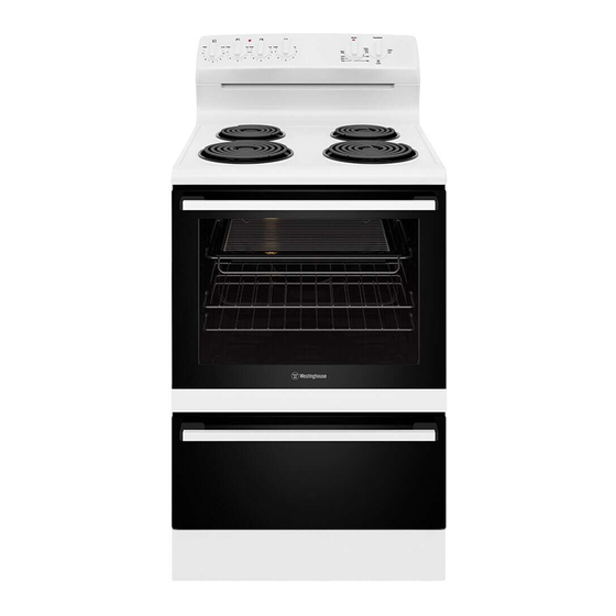
Installation Guide
60cm upright cookers
TIP S & IN FORMATION
IMPORTANT
Setting the time
If you have purchased a model fitted with an electronic or
programmable clock, you MUST set the time of day before
you can operate your appliance.
Service fuse location –
models with powerpoint only
This product is fitted with a power outlet at each end
of the control panel. The outlets are protected by a
replaceable high breaking capacity 15 amp fuse located
at the rear of the product.
WARNING
W ARNING
Before servicing the fuse, ensure that all power to product
is switched o .
To access fuse, unscrew fuse housing and remove from
appliance. (See diagram).
Fuse
Fuse housing
To access your detailed user manual simply scan the QR code
on your smart phone.
For more detailed information and installation guide refer to
user manual at westinghouse.com.au/manuals
and WESTINGHOUSE are trademarks of Westinghouse Electric Corporation. Used under license by Electrolux Home Products Pty Ltd. All Rights Reserved.
© 2023 Electrolux Home Products Pty Ltd. ABN 51 004 762 341 W_INS_60cm_UC_A4_Nov23 ANC A20211802 Rev A
Installation Guide
60cm upright cookers
W ARNING
WARNING
This appliance must be installed by an authorised person
in compliance with local municipal building codes and any
other relevant statutory regulation.
Wiring connections must be made in accordance with:
New Zealand & Australian requirements, including AS/NZS
3000 WIRING RULES.
Refer to data plate for rating information. The data plate is
positioned on the bottom of the oven front, viewable with
the oven door open.
•
Electrical connection is 230–240 volts AC 50 Hz.
•
To gain access to the mains connection terminals,
remove the rear cover by unscrewing the two assembly
screws.
•
Disconnection in the fixed wiring must occur in
accordance with the AS/NZS 3000 wiring rules.
•
The cooker MUST be earthed. Any damage caused by
failure to earth will not be covered by warranty.
•
This range must be connected with cable of 75°C
rating minimum.
•
This product has passed the insulation resistance test
after manufacture. If the resistance reading is low at
installation, it is probably caused by moisture from the
atmosphere being absorbed by the elements after the
range has been produced. (Pass at 0.01M AS/NZS
3000 Wiring Rules Clause 8.3.6.3).
NOTE: Where connection is made to a multi-phase
220/240V supply, the bridge piece must be removed from
between the active connections on the main terminal block.
If the range is placed on a base, measures have to be taken
to prevent the appliance slipping from the base
Fuse (for New Zealand only)
Should the fuse need servicing it is accessible through
the fuse opening located in the back cover. The Cooking
range must be connected to the supply by a supply cord
fitted with the appropriately rated plug with the socket-
outlet fitted to the final sub-circuit in the fixed wiring that is
intended to supply this cooking range. See table below.
Supply cord specifications
MODEL
CURRENT
WIRE
MINIMUM
RATING
SECTION
TEMP
(AMPS)
(MM
)
RATING
2
(°C)
WLE620WC
25
2.5
75
WLE624WC
32
4.0
75
WLE622WC
32
4.0
75
WLE625WC
32
4.0
75
WLE642WC
32
4.0
75
WLE642WCB 32
4.0
75
WLE645WC
32
4.0
75
WLE645WCB 32
4.0
75
Hard wiring detail
1.
Remove terminal cover plate from rear panel of
appliance.
2.
Fit wires through hole in cover plate and make
connections to terminals.
3.
Engage wires into plastic clip. Secure plastic clip with
two long silver screws (supplied in separate bag).
4.
Replace cover plate onto rear panel.
Plastic clip
Plastic clip
securing points
Input
MODEL
TOTAL KW
A1 KW
A2 KW
WLE620
9.7
3.1
6.6
WLE624
11.7
5.1
6.6
WLE622
10.7
4.1
6.6
WLE625
12.1
5.5
6.6
WLE642
10.5
4.1
6.4
WLE645
11.8
5.4
6.4
Advertisement

Subscribe to Our Youtube Channel
Related Manuals for Westinghouse WLE620WC


Summary of Contents for Westinghouse WLE620WC
- Page 1 WLE642WCB 32 WLE645WC and WESTINGHOUSE are trademarks of Westinghouse Electric Corporation. Used under license by Electrolux Home Products Pty Ltd. All Rights Reserved. © 2023 Electrolux Home Products Pty Ltd. ABN 51 004 762 341 W_INS_60cm_UC_A4_Nov23 ANC A20211802 Rev A...
- Page 2 Installation Guide Installation Guide 60cm upright cookers 60cm upright cookers INSTALLATION Step 2: Fixing anti-tilt bracket W ARNING CAUTION Position the anti-tilt bracket so that it will fully engage into the slot at the rear of the Installation dimensions cooker. The bracket is mounted centrally at the rear of the cooker.
Need help?
Do you have a question about the WLE620WC and is the answer not in the manual?
Questions and answers