GORMAN-RUPP PUMPS 10 Series Installation, Operation, And Maintenance Manual With Parts List
Hide thumbs
Also See for 10 Series:
Table of Contents
Advertisement
Quick Links
ACDEU
OM-04729-02
November 18, 2005
INSTALLATION, OPERATION,
AND MAINTENANCE MANUAL
WITH PARTS LIST
10 SERIES PUMPS
MODELS
13A52−CH13
13A52−CH13 S/G
THE GORMAN-RUPP COMPANY D MANSFIELD, OHIO
www.gormanrupp.com
D
GORMAN-RUPP OF CANADA LIMITED
ST. THOMAS, ONTARIO, CANADA
Printed in U.S.A.
e
Copyright by the Gorman-Rupp Company
Advertisement
Table of Contents

Related Manuals for GORMAN-RUPP PUMPS 10 Series


Summary of Contents for GORMAN-RUPP PUMPS 10 Series
- Page 1 ACDEU OM-04729-02 November 18, 2005 INSTALLATION, OPERATION, AND MAINTENANCE MANUAL WITH PARTS LIST 10 SERIES PUMPS MODELS 13A52−CH13 13A52−CH13 S/G THE GORMAN-RUPP COMPANY D MANSFIELD, OHIO www.gormanrupp.com GORMAN-RUPP OF CANADA LIMITED ST. THOMAS, ONTARIO, CANADA Printed in U.S.A. Copyright by the Gorman-Rupp Company...
- Page 2 The engine exhaust from this product contains chemicals known to the State of California to cause cancer, birth defects or other reproductive harm.
-
Page 3: Table Of Contents
TABLE OF CONTENTS INTRODUCTION ..........PAGE I −... - Page 4 TABLE OF CONTENTS (continued) PARTS LIST: Pump Model ............PAGE E −...
-
Page 5: Introduction
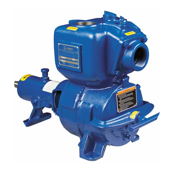
Rupp pump. to those which could be dangerous to personnel: This pump is a 10 Series, semi-open impeller, self- priming centrifugal model with a suction check valve. It is close-coupled to a single cylinder air cooled Kohler gasoline engine. -
Page 6: Safety - Section A
10 SERIES OM−04729 SAFETY − SECTION A This information applies to 10 Series en- gine driven pumps. Refer to the manual accompanying the engine before at- tempting to begin operation. This pump is designed to handle most non-volatile, non-flammable liquids This manual will alert personnel to containing specified entrained solids. - Page 7 OM−04729 10 SERIES burns and injuries. If overheating of the pump occurs: 1. Stop the pump immediately. Do not operate an internal combustion 2. Ventilate the area. engine in an explosive atmosphere. 3. Allow the pump to completely cool. When operating internal combustion 4.
-
Page 8: Installation − Section Bpage B
10 SERIES OM−04729 INSTALLATION − SECTION B Review all SAFETY information in Section A. specific application. Since the pressure supplied to the pump is critical to performance and safety, Since pump installations are seldom identical, this be sure to limit the incoming pressure to 50% of the... -
Page 9: Preinstallation Inspection
OM−04729 10 SERIES Battery Specifications And Installation PREINSTALLATION INSPECTION Unless otherwise specified on the pump order, the The pump assembly was inspected and tested be- engine battery for model 13A52−CH13 S/G was fore shipment from the factory. Before installation, not included with the unit. Refer to the following inspect the pump for damage which may have oc- specifications when selecting a battery. -
Page 10: Mounting
10 SERIES OM−04729 Materials Either pipe or hose maybe used for suction and discharge lines; however, the materials must be The pump assembly can be seriously compatible with the liquid being pumped. If hose is damaged if the cables or chains used to lift... -
Page 11: Fittings
OM−04729 10 SERIES the source of the liquid being pumped; if the line Suction Lines In Sumps slopes down to the pump at any point along the suction run, air pockets will be created. If a single suction line is installed in a sump, it... -
Page 12: Discharge Lines
10 SERIES OM−04729 Figure 2. Recommended Minimum Suction Line Submergence vs. Velocity DISCHARGE LINES Siphoning If the application involves a high discharge Do not terminate the discharge line at a level lower head, gradually close the discharge than that of the liquid being pumped unless a si- throttling valve before stopping the pump. -
Page 13: Operation − Section C
OM−04729 10 SERIES OPERATION − SECTION C Review all SAFETY information in Section A. not prime when dry. Extended operation of a dry pump will destroy the seal assembly. Follow the instructions on all tags, labels and Add liquid to the pump casing when: decals attached to the pump. -
Page 14: Lines With A Bypass
OM−04729 10 SERIES Lines With a Bypass boil, build pressure, and cause the pump to rup- ture or explode. If overheating occurs, stop the Close the discharge throttling valve (if so pump and allow it to cool before servicing it. Refill equipped) so that the pump will not have to prime the pump casing with cool liquid. -
Page 15: Pump Vacuum Check
OM−04729 10 SERIES on the pump performance curve. (See Section E, On engine driven pumps, reduce the throttle Page 1.) speed slowly and allow the engine to idle briefly be- fore stopping. Pump Vacuum Check With the pump inoperative, install a vacuum gauge If the application involves a high discharge in the system, using pipe dope on the threads. -
Page 16: Troubleshooting − Section D
10 SERIES OM−04729 TROUBLESHOOTING − SECTION D Review all SAFETY information in Section A. Before attempting to open or service the pump: 1. Familiarize yourself with this manual. 2. Shut down the engine and discon- nect the spark plug wire to ensure that the pump will remain inopera- tive. - Page 17 OM−04729 10 SERIES TROUBLE POSSIBLE CAUSE PROBABLE REMEDY PUMP STOPS OR Leaking or worn seal or pump gasket. Check pump vacuum. Replace FAILS TO DELIVER leaking or worn seal or gasket. RATED FLOW OR PRESSURE (cont.) Impeller or other wearing parts worn Replace worn or damaged parts.
-
Page 18: Preventive Maintenance
10 SERIES OM−04729 equipped) between regularly scheduled inspec- PREVENTIVE MAINTENANCE tions can indicate problems that can be corrected Since pump applications are seldom identical, and before system damage or catastrophic failure oc- pump wear is directly affected by such things as curs. -
Page 19: Pump Maintenance And Repair - Section E
OM−04729 10 SERIES PUMP MAINTENANCE AND REPAIR - SECTION E MAINTENANCE AND REPAIR OF THE WEARING PARTS OF THE PUMP WILL MAINTAIN PEAK OPERATING PERFORMANCE. STANDARD PERFORMANCE FOR PUMP MODEL 13A52−CH13 And 13A52−CH13 S/G Based on 70_ F (21_ C) clear water at sea level Contact the Gorman-Rupp Company to verify per- with minimum suction lift. - Page 20 OM−04729 10 SERIES SECTION DRAWING PARTS PAGE Figure 1. Pump Model 13A52−CH13 PAGE E − 2 MAINTENANCE & REPAIR...
- Page 21 OM−04729 10 SERIES PARTS LIST Pump Model 13A52−CH13 (From S/N 1334152 up) If your pump serial number is followed by an N", your pump is NOT a standard production model. Contact the Gorman-Rupp Company to verify part numbers. ITEM PART MAT’L...
- Page 22 OM−04729 10 SERIES SECTION DRAWING Figure 2. Pump Model 13A52−CH13 S/G PAGE E − 4 MAINTENANCE & REPAIR...
- Page 23 OM−04729 10 SERIES PARTS LIST Pump Model 13A52−CH13 S/G (From S/N 1334152 up) ITEM PART MAT’L PART NAME NUMBER CODE PUMP END ASSY 13A52−(CH13) −−− STREET ELBOW RS48 11999 MUFFLER KIT 48222−005 −−− KOHLER CH13 ENGINE 29127−092 −−− FLAT WASHER...
- Page 24 OM−04729 10 SERIES SECTION DRAWING Figure 3. Pump End Assembly 13A52−(CH13) PAGE E − 6 MAINTENANCE & REPAIR...
- Page 25 OM−04729 10 SERIES PARTS LIST Pump End Assembly 13A52−(CH13) ITEM PART MAT’L PART NAME NUMBER CODE PUMP CASING 2985 10010 IMPELLER 2996C 11010 SEAL ASSY 25285−855 −−− ACCESSORY PLUG 15079 FILL PLUG ASSY 48271−069 −−− NAME PLATE 38818−023 13990 DRIVE SCREW BM#04−03...
- Page 26 OM−04729 10 SERIES PUMP AND SEAL DISASSEMBLY 2. Shut down the engine and discon- nect the spark plug wire to ensure AND REASSEMBLY that the pump will remain inopera- tive. Review all SAFETY information in Section A. 3. Allow the pump to cool if over- heated.
- Page 27 10 SERIES OM−04729 and remove the hardware (14, 15, 16 and 17, Fig- stiff wires with hooked ends to pull the seal station- ure 1 or 34, 35, 36 and 37, Figure 2) securing the ary seat out of the intermediate.
- Page 28 OM−04729 10 SERIES SPRING RETAINER O-RING SPRING CENTERING WASHER STATIONARY IMPELLER SEAT SHIMS IMPELLER SHAFT SHAFT SLEEVE IMPELLER INTERMEDIATE ROTATING BELLOWS ELEMENT Figure 4. 25285−855 Seal Assembly sion finished faces; never use grease. Use even pressure to carefully press this subassembly onto the sleeve (36) until the rotating element is just flush with the chamfered end of the sleeve.
- Page 29 10 SERIES OM−04729 clearance and add or remove impeller shims until NOTE this clearance is reached. Apply a film of ‘Never-Seez’ or equivalent com- pound on the back cover shoulder or any surface which contacts the pump casing to ease future dis- Pump Casing Installation assembly and to reduce rust and scale build up.
- Page 30 OM−04729 10 SERIES Engine LUBRICATION Seal Assembly Consult the literature supplied with the engine, or (Figure 3) contact your local engine representative. The seal assembly is lubricated by the medium be- ing pumped. No additional lubrication is required. PAGE E − 12...
- Page 31 For U.S. and International Warranty Information, Please Visit www.grpumps.com/warranty or call: U.S.: 419−755−1280 International: +1−419−755−1352 For Canadian Warranty Information, Please Visit www.grcanada.com/warranty or call: 519−631−2870 THE GORMAN-RUPP COMPANY D MANSFIELD, OHIO GORMAN-RUPP OF CANADA LIMITED ST. THOMAS, ONTARIO, CANADA...
Need help?
Do you have a question about the 10 Series and is the answer not in the manual?
Questions and answers