Table of Contents
Advertisement
Quick Links
Advertisement
Table of Contents

Related Manuals for Hach 2100AN


Summary of Contents for Hach 2100AN
- Page 1 DOC022.52.80205 2100AN 11/2014, Edition 6 User Manual...
-
Page 3: Table Of Contents
Table of Contents Specifications ....................................5 General information ..................................6 Safety information ....................................7 Use of hazard information .................................. 7 Precautionary labels ..................................7 Certification ......................................7 Product overview ....................................8 Product components ..................................9 Installation ....................................... 10 Put paper in the printer ..................................10 User interface .................................... - Page 4 Table of Contents Clean the sample cell ................................19 Indexing a single sample cell ..............................20 Matching sample cells ................................22 Prepare dilution water ................................24 Prepare the sample ..................................24 Prepare a representative sample .............................. 24 Remove air bubbles from the sample ............................24 Apply a vacuum .................................
- Page 5 Table of Contents Using a manual flow cell ..............................36 Using an automated flow cell ............................. 36 Measurement notes ................................37 Static or dynamic measurement procedure ........................38 Use a cell adapter ..................................39 Install a cell adapter ................................40 Remove a cell adapter ...............................
- Page 6 Table of Contents Delete all the ASC data points ..............................50 Maintenance ....................................50 Clean the instrument ..................................50 Change the filter assembly ................................50 Clean the filter assembly .................................. 50 Replace the lamp ..................................... 50 Replace a fuse ....................................53 Troubleshooting ..................................
-
Page 7: Specifications
Specifications Specification Details Specifications are subject to change without notice. Range NTU (Ratio on, manual range): 0–0.999, 0–9.99, 0–99.9, 0–10,000 Specification Details NTU (Ratio on, auto range): 0–10,000 auto decimal NTU (Ratio off): 0–40 Measurement method Nephelometric Nephelo (Ratio on, manual range): 0–9.99, 0–99.9, Regulatory Meets EPA Method 180.1 0–67,000... -
Page 8: General Information
Specification Details Specification Details Resolution Turbidity: 0.001 NTU/EBC Air purge Dry nitrogen or instrument grade air (ANSI MC 11.1, 1975) Nephelo: 0.01 0.1 scfm at 69 kPa (10 psig); 138 kPa (20 psig) Absorbance: 0.001 Abs maximum Transmittance: 0.1% T Hose barb connection for -inch tubing Color: 1 CU... -
Page 9: Safety Information
Safety information on the instrument, will be included with a danger or caution statement in the manual. N O T I C E This symbol, if noted on the instrument, references the instruction The manufacturer is not responsible for any damages due to misapplication or manual for operation and/or safety information. -
Page 10: Product Overview
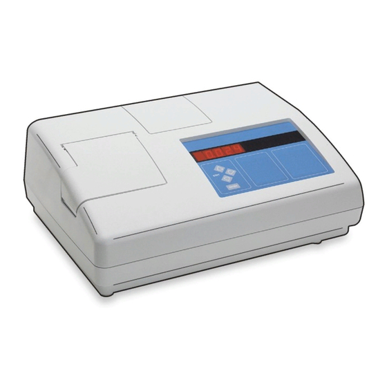
Product overview 2 Keypad 6 Printer cover The 2100AN laboratory turbidimeter measures turbidity in NTUs 3 Sample cell holder 7 Eight-digit LED display (nephelometric turbidity units), NEPs (nephelos) and EBCs (European Brewing Convention units). NEPs and EBCs are calculated using the 4 Light shield conversion factors of 6.7 nephelos per 1.0 NTU and 0.245 EBCs per... -
Page 11: Product Components
7 Remote cable jack for flow valve module connection to the automatic flow cell (low pressure) 4 DB9 connector for RS232 cable 8 Lamp access cover Product components 1 2100AN turbidimeter 7 StablCal ® Calibration kit ® 2 USEPA filter assembly... -
Page 12: Installation
Installation User interface D A N G E R Figure 4 Keypad Multiple hazards. Only qualified personnel must conduct the tasks described in this section of the document. Put paper in the printer N O T I C E Use only the provided thermal paper. Use of other thermal paper may cause poor print quality and decrease the life of the print-head. - Page 13 Table 1 Key descriptions (continued) Figure 5 Indicator lights Description Starts the changing of the sample number shown on the mode display. Selects automatic or manual ranging. Selects the unit of measure. Exits Calibration or Setup mode without saving changes. Turns Ratio on or off.
-
Page 14: Startup
Table 2 Light descriptions 1. Put the instrument on a stable, level surface that is free of vibration. Do not put in direct sunlight. Light Description 2. Make sure that there is air circulation around the instrument. Keep Illuminated when the instrument light source is on. the back and area below the instrument free of material that could decrease air flow through the vents. -
Page 15: Show The Current Time (Optional)
Prepare the StablCal standards Option Description When received and at intervals: Sets the month and day (MM-DD). 1. Clean the exterior surface of the StablCal vials with laboratory glass Sets the year (YY). cleaning detergent. 3. Push ENTER. 2. Rinse the vials with distilled or deionized water. 4. -
Page 16: Stablcal Calibration Procedure
• All nephelometric (turbidity units of measure) calibrations are done at CAL/Zero after the 4000 NTU standard is measured to complete the the same time. calibration procedure. • Ratio-on and Ratio-off calibration data is measured and recorded at • Clean the USEPA filter assembly before doing a primary calibration, the same time. -
Page 17: Stablcal Standards Storage
7. Use the oiling cloth 8. Put the vial in the 9. Push ENTER. 10. Remove the vial 11. Do steps 5–10 for 12. Push CAL/Zero. to apply the oil equally sample cell holder with from the sample cell the other StablCal vials The instrument display The instrument saves to the surface of the... -
Page 18: Measure The Gelex Stray Light Standard
Measure the Gelex stray light standard Measure the Gelex stray light standard when the instrument is first received. Record the value on the Gelex vial with a permanent marker one time. 1. Clean the stray light 2. Apply a small bead 3. -
Page 19: Measure The Gelex Secondary Turbidity Standards
Measure the Gelex secondary turbidity standards Measure the Gelex secondary turbidity standards each time the instrument is calibrated and record the new values on the Gelex vials with a water soluble marker. 1. Clean the Gelex 2. Apply a small bead 3. -
Page 20: Calibration Verification
7. Push RATIO to 8. Put the 0–2 NTU 9. Read the value 10. Record the value 11. Do steps 7–10 for select Ratio on or off. Gelex vial in the sample when stable. Remove on the white diamond the other Gelex vials cell holder with the the vial from the space on the vial using... -
Page 21: Clean The Sample Cell
2. Fully rinse the sample cell many times with distilled or deionized Clean the sample cell water. C A U T I O N 3. Clean the internal and external surfaces of the sample cell and cap with 1:1 hydrochloric acid. 4. -
Page 22: Indexing A Single Sample Cell
Indexing a single sample cell When measuring very low turbidity samples, use a single indexed sample cell or a flow cell for all measurements to get precise and repeatable measurements. As an alternative, optically matched sample cells can be used. Refer to Matching sample cells on page 22. - Page 23 7. Repeat step 6 until 8. Put an orientation the lowest value is mark on the marking shown on the display. band near the top of the sample cell where the lowest value is shown. English 21...
-
Page 24: Matching Sample Cells
Matching sample cells To decrease the effects that optical differences among sample cells can have on turbidity, transmittance, color or absorbance measurements, measure samples in matched sample cells. It may not be possible to match all sample cells due to the differences in glass. 1. - Page 25 7. Repeat step 6 until 8. Record the value. 9. Put the second 10. Remove the 11. Repeat step 10 12. Put an orientation the lowest value is Put an orientation mark sample cell in the sample cell, turn it until the value matches mark on the marking shown on the display.
-
Page 26: Prepare Dilution Water
The methods typically used for degassing are: Prepare dilution water Dilution water is used when indexing a sample cell or matching sample • Let the sample stand for several minutes cells and to prepare formazin standards. • Apply a vacuum •... -
Page 27: Apply Heat
1. Fill a clean sample cell with sample. Do not put the cap on the Note: Warming may change the sample turbidity. Measure the sample without warming when possible. sample cell. Measure over-range samples 2. Put of the sample cell into the ultrasonic bath and let it stand until visible bubbles are removed. -
Page 28: Turbidity Measurement
Example: Dilution factor = 100 ÷ 20 = 5 For accurate turbidity readings use clean sample cells and remove air bubbles. Refer to Clean the sample cell on page 19 and Remove air 3. Calculate the actual turbidity: bubbles from the sample on page 24. -
Page 29: Turbidity Measurement Procedure
• Measure samples immediately to prevent temperature changes and Note: As an alternative, matched sample cells may be used for measurements but do not provide as good of accuracy or precision as a single indexed sample cell or settling. Before a measurement is taken, always make sure that the flow cell. -
Page 30: Absorbance And Transmittance Measurement
7. Read and record the value when stable. Note: To print or send (via RS232) a measurement record, push PRINT. Absorbance and transmittance measurement measured on a single sample after setting a zero reference point in one of the three modes. •... -
Page 31: Absorbance And Transmittance Measurement Procedure
Absorbance and transmittance measurement procedure Note: To measure samples with negative absorbance, set the analytical zero using the sample with the greatest absorbance, and measure the sample with the least absorbance. Report the reading as negative absorbance. 1. Put a clean filter 2. -
Page 32: Color Measurement
To make a 15 CU standard, add deionized water on page 5. Use of a Flow Cell is especially important when low-level to 15 mL of the 500 CU standard from Hach until 500 mL. A flow cell color is measured. -
Page 33: Color Measurement And Calibration Procedure
Color measurement and calibration procedure 1. Make sure that the 2. Push RANGE to 3. Push SIGNAL AVG 4. Push UNITS/Exit 5. Push CAL/Zero. 6. Using the manual 455 nm filter assembly select manual or to set signal averaging until "CU" is shown on flow cell kit, install the The display shows is installed in the... - Page 34 7. Slowly put 250 mL of 8. Push ENTER. 9. Use the arrow keys 10. Slowly put 250 mL 11. Push ENTER. 12. Push UNITS/Exit deionized water down to change the display to of the CU standard in to go back to The instrument display The instrument display the interior edge of the...
-
Page 35: Measurement Techniques
Measurement techniques Push SIGNAL AVG to turn signal averaging on or off. The SIGNAL AVG light turns on when signal averaging is on. Measurements may be made with different operation mode settings and Push ENTER when signal averaging is on to erase data in the signal optional accessories. -
Page 36: Using The Air Purge System
if interferences caused by color or light absorbing particles are not Figure 8 Standard shop air present. Using the air purge system The air purge system is used to keep condensation off the external surface of the sample cell when cold samples are measured. The air purge system pushes dry air through the optical compartment to keep the outside the sample cell dry. -
Page 37: Install A Flow Cell
Install a flow cell 4. Fill the sample cell with distilled or demineralized water and immediately put the caps on the sample cell. 1. Fully clean and assemble the flow cell, tubing and stand. Refer to 5. Clean the inside and outside of the plastic parts and tubing with Clean a flow cell assembly on page 35 and the user instructions laboratory detergent and warm water. -
Page 38: Flow Cell Storage
Flow cell storage 2. The flow valve closes when the fill time interval ends. The last portion of sample flowing through the flow cell is held so that sample volume • Install the reservoir cover when the system is not in use to prevent measurements can be made for the selected measurement time. -
Page 39: Measurement Notes
A fill time setting of 0 seconds causes the instrument to start Select the measurement time measurement immediately. The measurement time is the time interval that the instrument measures the sample. Use the flow cell specifications in Table 3 to calculate the correct fill time. Make sure that the fill time includes time to fill the system and to fully A measurement is completed and the display is updated about once remove the previous sample from the system. -
Page 40: Static Or Dynamic Measurement Procedure
Static or dynamic measurement procedure 1. Push PRINT to turn 2. Install the automated 3. Push FLOW. 4. Push the up and 5. Push ENTER. 6. Push the arrow keys the print interval feature flow cell. Refer to Install down arrow keys to to select the fill time. -
Page 41: Use A Cell Adapter
7. Push ENTER. 8. Push the arrow keys 9. Push ENTER to 10. When 11. Push and hold the to select the open the flow valve and measurements are valve-control switch to The display shows measurement time. start the fill time complete, push FLOW. -
Page 42: Install A Cell Adapter
Install a cell adapter N O T I C E Note: Use the application specific calibration (ASC) ability of the instrument to Do not force the cell adapter out of the instrument as serious damage can provide direct reading of results with cell adapters installed. If the ASC ability is not occur. -
Page 43: Connect To A Printer Or Computer
Connect to a printer or computer Configure the RS232 connection Use the serial interface (RS232) connector on the back of the instrument 1. Push SETUP. The SETUP light turns on. to transmit data from the instrument to an external printer or a serial 2. -
Page 44: Connect To A Data Recorder
Table 5 RS232 command set (continued) Configure the data recorder output Command Description Note: The recorder minimum and maximum values are selected independently for each measurement mode. When the measurement mode changes, the previous Gets the recorder minimum value. settings are automatically used. To change the recorder minimum value, enter RMN=XXXXX (XXXXX=a number, minimum value=0), then push Enter. -
Page 45: Prepare Formazin Standards
Standard Step 1 Step 2 Step 3 stock solution from Hach to make formazin standards. 1000 NTU Add 50 mL of dilution With a TenSette Dilute to the mark Note: As an alternative, a 4000-NTU formazin stock solution that is prepared by water to a clean 100- Pipet, add 25.00 mL... -
Page 46: Formazin Calibration Procedure
• Use only the provided silicone oil. This silicone oil has the same • Ratio-on and Ratio-off calibration data is measured and recorded at refractive index as the vial glass and masks minor glass differences the same time. and scratches. •... - Page 47 7. Apply a small bead 8. Use the oiling cloth 9. Put the sample cell 10. Push ENTER. 11. Remove the 12. Do steps 5–11 for of silicone oil from the provided to apply the oil in the sample cell sample cell from the the other formazin The instrument display...
-
Page 48: Making 4000-Ntu Formazin Stock Solution
Note: Making formazin stock solution from raw materials is not recommended. standards are in the range of: Preparation of formazin stock solution is temperature and technique sensitive. Use Hach formazin stock solution to get the best instrument performance and analytical • 10–30 NTU standard accuracy. -
Page 49: Special Research Applications
Special research applications Application specific calibration The instrument has special features and operations for special research Nephelometric analysis can result in a calibration curve that is not linear. applications. This instrument can store two application specific caibration (ASC) curves with up to eight data pairs in each. Application specific methods This instrument uses point-to-point interpolation between entered standards for the ASC calibrations. -
Page 50: Initial Asc Entry
Either ASC can be changed at any time, so recalibration is not The left digit of the display flashes. necessary. 7. Use the arrow keys to change the number on the display to the The sample is under-range if the display flashes 0s. correct NTU value. -
Page 51: Change An Asc Unit Name Or One Asc Data Point
8. Push ENTER to accept the MGL value shown on the display. Note: A print of a graph of the ASC points is also made if the internal printer is enabled. The mode display flashes the next data point (e.g., "05" for data point 4. -
Page 52: Delete All The Asc Data Points
Change the filter assembly Delete all the ASC data points Either of the ASC calibration curves can be deleted and the ASC unit N O T I C E name changed back to the factory default. The filter assembly is fragile and must be handled with care to prevent damage. 1. - Page 53 Notes: • Turn the instrument on 30 minutes (Ratio on) or 60 minutes (Ratio off) before measurement or calibration. • Replace the lamp with the same size, style and electrical rating • Calibrate the instrument after the lamp is replaced. (4708900).
- Page 54 52 English...
-
Page 55: Replace A Fuse
Troubleshooting Replace a fuse Refer to the tables in this section for error codes, diagnostic codes, D A N G E R common problem messages or symptoms, possible causes and corrective actions. Fire hazard. Use the same type and current rating to replace fuses. Error codes Replacement parts: Table 8... -
Page 56: Diagnostic Codes
Table 8 Error codes (continued) Table 8 Error codes (continued) Error Description Solution Error Description Solution ERR03 Low light error ERR10 System voltage out of 1. Put the sample in the instrument again. 1. Turn the instrument off and then back on. range 2. -
Page 57: Delete Calibration Data
Table 9 Diagnostic codes (continued) zero using the sample with the greatest absorbance and read the sample with the least absorbance. Record the reading as negative Code Display Description absorbance. Test results are shown. Keyboard test Replacement parts and accessories Test results are shown. - Page 58 Replacement parts (continued) Accessories (continued) Description Quantity Item no. Description Quantity Item no. Power cord, European, 230 VAC, VDE Filter assembly, 810 nm 3037600 4683600 approved Filter assembly, 860 nm Printer paper, thermal 4709000 1999900 (specified by ISO 7027 for turbidity measurement) Sample cells, 30mL, 1 in.
- Page 59 Accessories (continued) Optional reagents Description Quantity Item no. Description Quantity Item no. Pump, vacuum/pressure, 115V, 60 Hz, Hexamethylenetetramine 500 g 187834 2424800 1.2 cfm Hydrazine sulfate 100 g 74226 Pump, vacuum/pressure, 220V, 50 Hz, 2824802 1.2 cfm Sample degassing kit 4397500 Sample degassing and filtration kit 4397510...
- Page 60 58 English...
- Page 62 Tel. +49 (0) 2 11 52 88-320 SWITZERLAND Fax (970) 669-2932 Fax +49 (0) 2 11 52 88-210 Tel. +41 22 594 6400 orders@hach.com info@hach-lange.de Fax +41 22 594 6499 www.hach.com www.hach-lange.de © Hach Company/Hach Lange GmbH, 2012, 2014. All rights reserved. Printed in U.S.A.
Need help?
Do you have a question about the 2100AN and is the answer not in the manual?
Questions and answers