
Related Manuals for Hach 2100AN


Summary of Contents for Hach 2100AN
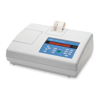
- Page 1 47001-88 MODEL 2100AN LABORATORY TURBIDIMETER INSTRUMENT MANUAL For Use With Software Version 1 © Hach Company, 1993-1997, 1999, 2000. All rights reserved. Printed in the U.S.A. 8/95 2ed aa/dp Rev. 6, 2/00...
-
Page 2: Trademarks Of Hach Company
TRADEMARKS OF HACH COMPANY ® AccuGrow H O University™ Pond In Pillow™ ® AccuVac H OU™ PourRite™ ® AccuVer™ Hach Logo PrepTab™ ® AccuVial™ Hach One ProNetic™ ® Add-A-Test™ Hach Oval Pump Colorimeter™ ® AgriTrak™ Hach.com™ QuanTab ® AluVer HachLink™... -
Page 3: Table Of Contents
TABLE OF CONTENTS TRADEMARKS OF HACH COMPANY ........................2 SAFETY PRECAUTIONS .............................. 7 OPERATION ................................. 9 SECTION 1 GENERAL DESCRIPTION ......................11 1.1 Instrument Description............................. 11 1.2 Standard Accessories..............................11 1.3 Principle of Operation .............................. 11 1.4 Preparation for Use..............................12 1.4.1 Unpacking............................... - Page 4 3.2 Calibration ................................36 3.2.1 Formazin Stock Solution ..........................37 3.2.2 Dilution Water ..............................37 3.2.3 Preparing Recommended Formazin Dilutions ....................37 3.2.4 Calibrating the 2100AN (using Formazin Standards)..................39 ® 3.2.5 Using Gelex Secondary Turbidity Standards....................42 3.2.6 Formulating Formazin Stock Solution ......................43 3.3 Special Research Applications..........................
- Page 5 TABLE OF CONTENTS, continued SECTION 8 CELL ADAPTERS ........................... 77 8.1 Using Cell Adapters ..............................77 8.1.1 Installing and Removing Cell Adapters......................77 SECTION 9 COLORIMETRIC MEASUREMENT ..................79 9.1 Filter Modules ................................79 9.1.1 Installing Filter Assemblies ..........................79 9.1.2 Developing Applications Using Alternate Wavelengths ................
-
Page 7: Safety Precautions
SAFETY PRECAUTIONS Section 1.4.3 Operating Power Selection on page 13 Section 2.2 Measuring Turbidity on page 15 Section 4.1 Air Purge Connection on page 47 Section 5.2.4 High Pressure Flow-Cell Kit on page 60 Section 6.2 RS232 Connection on page 67 Section 11.2 Lamp Replacement on page 93... -
Page 9: Operation
OPERATION DANGER Handling chemical samples, standards, and reagents can be dangerous. Review the necessary Material Safety Data Sheets and become familiar with all safety procedures before handling any chemicals. DANGER La manipulation des échantillons chimiques, étalons et réactifs peut être dangereuse. Lire les Fiches de Données de Sécurité... -
Page 11: Section 1 General Description
SECTION 1 GENERAL DESCRIPTION 1.1 Instrument Description The Hach Model 2100AN Laboratory Turbidimeter measures turbidity from 0 to 10,000 NTU (Nephelometric Turbidity Units) with automatic range selection and decimal point placement. Measure solutions with higher turbidity levels by dilution with filtered sample and a simple calculation. Refer to Section 2.3.7 on page 26 for additional information. -
Page 12: Preparation For Use
Remove the instrument and accessories from their shipping box and inspect them for damage that may have occurred during shipment due to rough handling or extreme weather conditions. Verify the following items are present: • Model 2100AN Laboratory Turbidimeter • Instrument Manual •... -
Page 13: Operating Environment
A power cord suitable for U.S. and Canadian 115 Vac line voltage is supplied with the Model 2100AN (Cat. No. 47001-00). If this model is to be configured for 230 Vac, an approved UL/CSA power cord with NEMA 6-15P type cord cap must be used in place of the 115V power cord supplied. -
Page 15: Section 2 Turbidity Measurement
Probe fraglich ist, sollten vor der Analyse Tests durchgeführt werden. AVISO O Turbidímetro de Laboratório 2100AN não é feito com o fim de ser empregado com amostras inflamáveis ou aquelas que contêm hidrocarbonetos ou ácidos concentrados que possam atacar os componentes 2100AN. Os testes devem ser executados antes da... -
Page 16: Nephelometric Measurement Procedure
SECTION 2, continued 2.2.1 Nephelometric Measurement Procedure Collect a Hold the sample cell Apply a thin bead of Install the appropriate representative sample in a by the cap, and wipe to silicone oil from the top to filter module. clean container. Fill the remove water spots and bottom of the cell—just Note: The USEPA filter... -
Page 17: Measurement Hints
SECTION 2, continued Select the appropriate Read and record the measurement unit (NTU, results. EBC or NEPH) by Note: A time- and date- pressing the UNITS/EXIT stamped measurement key. record can be printed or transmitted by pressing the key. PRINT 2.2.2 Measurement Hints •... -
Page 18: Measurement Techniques
Treat the outside of the cells with a thin coating of silicone oil to mask minor imperfections and scratches that may contribute to light scattering. Use only Hach silicone oil (Cat. No. 1269-36); it has the same refractive index as the sample cell glass. -
Page 19: Preparing Dilution Water
Formazin Standards. Collect at least 1000 mL of high quality water (e.g., distilled, demineralized, or deionized water). Check the turbidity of the dilution water before use. The 2100AN may be used to check the dilution water turbidity because the instrument is precalibrated at the factory. -
Page 20: Indexing And Matching Sample Cells
SECTION 2, continued 2.3.3.1 Dilution Water Filtration Attach the syringe to Fill a beaker or Draw about 50 mL of the 3-way valve by gently container with the water to sample into the syringe. twisting the square end be filtered. Insert the Slowly push on the into the syringe tip. - Page 21 SECTION 2, continued Fill the clean sample Wipe the sample cell Insert the appropriate Insert the sample cell cell to the line with high- clean and apply a film of filter module. into the cell compartment quality water and cap the silicone oil (refer to and close the cell cover.
- Page 22 SECTION 2, continued 2.3.4.2 Matching Sample Cells Index match (orientation) multiple cells using the following procedure. Matched cells also can be used for measuring in Transmittance, Color or Absorbance: Add portions of the Insert the appropriate Insert the first cell into Insert the second cell high-quality dilution filter module.
-
Page 23: Removing Air Bubbles (Degassing)
SECTION 2, continued 2.3.5 Removing Air Bubbles (Degassing) Remove air or other entrained gases prior to measurement. Degassing is recommended (even if no bubbles are visible). Four methods are commonly used for degassing: 1. Application of a partial vacuum 2. Addition of a surfactant 3. - Page 24 Surfactants change the surface tension of the water causing the release of entrained gases. Hach Company recommends a surfactant such as Triton X-100 (a Rohm and Haas Product, Hach Cat. No. 14096-32) or equivalent. Add one drop of Triton X-100 in the sample cell prior to sample addition.
-
Page 25: Signal Averaging
Changing Buffer Setting SIGNAL AVERAGE The 2100AN is shipped from the factory with a default buffer setting of 10 measurements. To change the number of measurements (adjustable from 1-15): 1. Enter the setup mode by pressing . The mode display flashes. -
Page 26: Measuring Over-Range Samples
This condition is called “going blind.” If a sample causes the 2100AN Turbidimeter to “go blind,” the sample may be diluted and re-measured. Or, use a cell adapter and a smaller diameter sample cell to shorten the length of the light path. - Page 27 2.3.7.2 Using Cell Adapters Cell adapters are used with the Model 2100AN Turbidimeter when sample cells smaller than the standard 25-mm cells are required. A wide variety of test tubes, sample cells and ampules can be used with the cell adapters. Small diameter...
- Page 28 The same handling and cleaning care applied to the instruction sheet sent with the cell standard 2100AN sample cells applies to the smaller cells (including the use of adapters for additional information. silicone oil on the outside of the glass.
-
Page 29: Condensation (Fogging)
When condensation is probable, use the air purge feature of the 2100AN. Refer to SECTION 4 on page 47 for instructions on connecting and using air purge. If condensation persists even with... -
Page 30: Representative Sampling
SECTION 2, continued 2.3.10 Representative Sampling A representative sample accurately reflects the true conditions of the source from which the sample was taken. To ensure a representative sample, gently but thoroughly mix every sample before collecting aliquots (sample portions). Do not allow particles to settle before making measurements. -
Page 31: Section 3 Operation
3.1 Operational Controls and Indicators Figure 6 illustrates the locations of all controls, indicators and other operational features of the Model 2100AN Laboratory Turbidimeter. Information on the functions of each of these features is provided in Table 1 and supplemented with additional details in sections Section 3.1.1 through Section 3.1.11. - Page 32 SECTION 3, continued Table 1 Operating Features and Functional Descriptions Item Name Description Used in Calibration Mode to select the value of the Formazin calibration standard and to initiate measurement of the standard. Pressing ENTER during measurement with Signal Averaging on ENTER clears the buffer of all previous data.
-
Page 33: Using The Range Key
SECTION 3, continued Table 1 Operating Features and Functional Descriptions (continued) Item Name Description Fuse Holder Contains two time-delay, 1.6 amp, 250V fuses suitable for either 115- or 230-volt operation. Power switch turns instrument on and off. Serial Interface DB9 connector for RS232 cable connection. Connector Air Purge Fitting Connection for air purge tubing. -
Page 34: Using The Signal Avg Key
SECTION 3, continued 3.1.3 Using the SIGNAL AVG Turning on Signal Averaging causes a number of measurements to accumulate in a measurement data storage buffer. The number of measurements stored and used for displaying the average reading can be specified by the analyst (between 1 and 15 readings). -
Page 35: Using The Print Key
SECTION 3, continued 3.1.7 Using the PRINT key initializes several data transmittal activities. Press the PRINT PRINT to print the displayed value, units of measure, sample number, and time and date to the internal printer and/or RS232 output. See Section 6.4.2 on page 71 for detailed setup instructions. -
Page 36: Using The Sample Key
3.2 Calibration The electronic and optical design of the 2100AN Turbidimeter provides long-term stability and minimizes the need for frequent calibration. The multi-detector ratioing optical system compensates for electronic and optical system variations between calibrations. -
Page 37: Formazin Stock Solution
Note: Instead of diluting a formazin stock solution, StablCal stabilized formazin suspensions may be used. Order StablCal Calibration Kit for the 2100AN Turbidimeter, Cat. No. 26595-00 (bottled) or Cat. No. 26595-05 (ampuled). Hach Company recommends use of 20-, 200-, 1000- and 4000 and 7500-NTU Formazin standards for calibration of the Model 2100AN Turbidimeter. - Page 38 SECTION 3, continued Table 2 Formazin Standard Preparation Standard Step 1 Step 2 Step 3 ® With a TenSette * Pipet, add 1.00 Add 100 mL of dilution water to a mL of well-mixed 4000-NTU Dilute to the mark with dilution water. 20 NTU clean 200-mL class A volumetric Formazin stock solution to the...
-
Page 39: Calibrating The 2100An (Using Formazin Standards)
SECTION 3, continued 3.2.4 Calibrating the 2100AN (using Formazin Standards) Insert the EPA filter Press Fill a clean sample Place the sample cell CAL/Zero module. cell to the line (approx. into the cell holder, and The CAL mode 30 mL) with dilution close the cell cover. - Page 40 SECTION 3, continued Press The instrument Fill a clean sample cell Press ENTER ENTER automatically increments to the line with well- The instrument display The display counts down to the next standard, mixed, 20-NTU Formazin counts down from from , and takes a displays the expected standard.
- Page 41 SECTION 3, continued Fill a clean sample cell Fill a clean sample Fill a clean sample Handling the to the line with well- cell to the line with well- cell to the line with well- 7500-NTU Formazin mixed, 200-NTU mixed, 1000-NTU mixed, 4000-NTU ampule by the top, mix by Formazin standard.
-
Page 42: Secondary Turbidity Standards
Make sure the sample cell is aligned in the cell holder the same way each Note: Consistent orientation of the time. Hach recommends using the vertical line that extends upward from the Gelex standards is critical each time diamond symbol on the vial as a reference mark. Align this mark with the sample they are used to check the instrument calibration. -
Page 43: Formulating Formazin Stock Solution
SECTION 3, continued 3.2.6 Formulating Formazin Stock Solution WARNING ATTENTION To familiarize yourself with Pour se familiariser avec les précautions à prendre lors de la manipulation, les dangers handling precautions, dangers and et les procédures d'urgence, toujours lire les Fiches de Données de Sécurite avant de emergency procedures, always manipuler les récipients, les réservoirs et les systèmes de distribution contenant les review the Material Safety Data... -
Page 44: Special Research Applications
SECTION 3, continued 3.3 Special Research Applications Special features and operations have been designed into the 2100AN Turbidimeter for special research applications. Refer to SECTION 10 on page 85 for more information about application specific measurements, use of cell adapters, and interchangeable filter modules. -
Page 45: Preparing Formazin Dilutions - User Selected
3.3.3 Preparing Formazin Dilutions - User Selected Hach Company recommends using 20, 200, 1000, 4000 and 7500-NTU formazin standards for calibrating the 2100AN Turbidimeter. Other dilutions can be prepared and used, but if problems occur when using these alternative solutions, use the dilutions specified in Section 3.2.3 on page 37. -
Page 47: Section 4 Air Purge System
SECTION 4 AIR PURGE SYSTEM Air Purge Connection An air purge system is provided to purge the optical compartment with dry air to prevent condensation on the outside of the sample cell when measuring cold samples. This system is particularly useful when using the Flow-Thru Cell assembly. -
Page 49: Section 5 Using Flow-Cell System Apparatus
ADVERTENCIA of the cells. Conduct tests prior to No use las Células de Flujo Flow Cells de Hach con muestras inflamables o que use of Flow Cells if sample contengan hidtocarburos, soventes, ácidos concentrados o bases concentradas que compatibility is questionable. -
Page 50: Flow-Cell Kits (Low Pressure)
SECTION 5, continued 5.2 Flow-Cell Kits (Low Pressure) The Low Pressure Flow-Cell systems (manual or automated kits) use an innovative sample cell design* with a baffled inlet and dual outlets that minimize accumulation of entrapped air bubbles and heavy solid particles in the cell (see Figure 8). -
Page 51: Manual Flow-Cell Kit (Low Pressure)
SECTION 5, continued Figure 9 Manual Low Pressure Flow Cell 5.2.1 Manual Flow-Cell Kit (Low Pressure) The Manual Flow-Cell Kit (Cat. No. 47449-00) is for low pressure [<34 kPa (5 psig)] applications (see Figure 9). The kit consists of a Flow-Cell Stand Assembly, a Flow-Cell Inlet Reservoir with a capacity of 350 mL, a Reservoir Cover, a Collection Drain Assembly, the Flow- Cell Assembly, interconnecting tubing, and a Flow-Cell Light Shield. - Page 52 SECTION 5, continued 5.2.1.1 Assembling the Support Stand 1. Verify the sample compartment is empty, and turn the instrument off. 2. Turn the instrument on its top (place it on a soft cloth to protect the instrument from marring), and install the base plate of the stand as illustrated in Figure 10. DO NOT OVERTIGHTEN THE SCREWS 3.
- Page 53 SECTION 5, continued 5.2.1.2 Assembling the Flow Cell Verify the O-rings have been installed in the top and bottom end caps; then screw the caps on to the glass sample cell. Tighten the caps enough to ensure a water- tight seal, but do not over tighten. 5.2.1.3 Connecting Inlet and Outlet Tubing 1.
-
Page 54: Automated Flow-Cell Kit (Low Pressure)
47450-02, 230 Vac), uses a Flow Valve Module for control of sample flow (see Figure 11). The kit contains a remote control cable used with the Model 2100AN Turbidimeter for automated operation. Refer to Section 5.2.1.1 and Section 5.2.1.2 for assembly instructions. Omit step 5 in Section 5.2.1.1; the Collection Drain Assembly is not provided with the Automated Flow-Cell Kit. - Page 55 6. Connect the power supply to the Power jack on the Flow Valve Module. Plug the power supply into an appropriate wall receptacle. 7. Connect the Remote jack on the back of the 2100AN Turbidimeter to the Remote jack on the back of the Flow Valve Module using the remote cable.
- Page 56 Flow-Cell, is approximately 30 mL. Flow rate through the system is approximately 250 mL/min. Hach Company suggests a minimum volume of 120 mL (fill time = 30 seconds) to purge the system of previous sample. This volume purges the system approximately 4 times.
- Page 57 SECTION 5, continued 1. Select the desired settings for Signal Averaging on or off and Ratio on or off. Note: Measurements in the Flow mode of operation can be made with Signal Averaging and Ratio modes 2. Select the printer and print interval desired (see Section 6.3 Printer). on or off.
- Page 58 SECTION 5, continued 5.2.2.7 Using Dynamic Measurement Mode In the dynamic mode the Flow Valve opens, the cell fills and sample continues Note: Check to ensure the proper wavelength filter module is installed to flow for the programmed fill time interval. The Flow Valve remains open, before beginning measurement.
-
Page 59: Tips For Flow-Cell Kits (Low Pressure)
• Hach Company suggests a minimum volume of 120 mL (fill time = 30 seconds) to purge the system of previous sample. This volume purges the system approximately four times. A shorter fill time may be appropriate when making repeated measurements of the same sample. -
Page 60: High Pressure Flow-Cell Kit
SECTION 5, continued 5.2.4 High Pressure Flow-Cell Kit The High Pressure Flow-Cell Kit can be used for continuous measurement of a process stream, and accommodates up to 414 kPa (60 psig) (see Figure 12). It can operate continuously in temperatures up to 30 °C (86 °F), and intermittently in temperatures up to 40 °C (104 °F). - Page 61 SECTION 5, continued Figure 15 illustrates a suggested hookup using a pressure regulator in the inlet line and a flow meter or flow control valve on the outlet line. The control valve is installed on the outlet side because it may introduce bubbles into the sample causing positive interference in the turbidity reading.
- Page 62 SECTION 5, continued CAUTION PRUDENCE Provide back-flow protection to Installer une protection antire-tour pour éviter les variations brusques de pression prevent pressure surges from audessus de 4 bar (400 kPa, 60 psig) dans les applications où l’échantillon retourne exceeding 60 psig in applications dans une ligne sous pression.
-
Page 63: Flow-Cell Maintenance
SECTION 5, continued WARNING ADVERTENCIA Use eye protection and handle with Use protección de los ojos y manipule con extrema precaución al iniciar la presión en el extreme care when pressurizing sistema mientras la célula de Flujo Continuo esté retirada del instrumento. No sostenga the system with the Flow Cell out la unidad tomándola por la célula de vidrio. -
Page 65: Section 6 Data Output
SECTION 6 DATA OUTPUT 6.1 Recorder Output The recorder output jack on the back panel (REC) takes a ¼″ phone plug wired Note: Use a twisted-pair, shielded recorder cable. Use of non-shielded as shown in Figure 16. A suitable plug is listed under Optional Accessories in recorder cables may result in radio SECTION 13 on page 99. -
Page 66: Setting Recorder Maximum Value
SECTION 6, continued 6.1.2 Setting Recorder Maximum Value This function is used to set the maximum value of the recorder output for the current units (selected measurement mode). 1. Enter the setup mode by pressing . The mode display flashes. SETUP 2. -
Page 67: Rs232 Connection
SECTION 6, continued RS232 Connection The RS232 connection on the back panel mates with a standard RS232 connector as indicated in Figure 17 (also see Table 3 and Figure 18). The factory RS232 interface output is an eight-bit data word plus one stop bit and no parity with a baud rate of 1200. - Page 68 SECTION 6, continued A. Baud Rate Select: 1. Press (the small LED mode display flashes). SETUP 2. Use the up, down and right arrow keys to enter into the mode display. 3. Press ENTER 4. The current baud rate flashes in the large display (1200 is the factory setting). 5.
-
Page 69: Instrument Communication
25-pin D connector is an optional accessory (refer to SECTION 13 on page 99). Using a serial-to-parallel converter, the data string transmitted from the 2100AN Turbidimeter prints on any Epson compatible parallel printer that is used with IBM compatible applications. -
Page 70: Printer
Figure 20 shows a sample printout from the built-in printer. 6.4.1 Built-In Printer The 2100AN Turbidimeter has a built-in 28 column thermal printer. The printer is active for output when the printer selection setup (number ) is set to (see Section 6.4.2.2). -
Page 71: Printer Setup Commands
SECTION 6, continued 6.4.2 Printer Setup Commands 6.4.2.1 Printer Speed Selection The 2100AN Turbidimeter can be configured for fast or slow (2.5 second delay) print speed. 1. Enter the setup mode by pressing . The small LED mode display SETUP will flash. -
Page 72: Using A Computer (Rs232 Operating Commands)
• Key in (for time/24 hour format), and press enter on the computer keyboard. This action recalls the current time programmed into the 2100AN. Key in to set a new time. Press enter on the computer keyboard TIM=HH:MM... - Page 73 Key in [for recorder maximum (current units)], and press enter on the computer keyboard. This action recalls the current recorder maximum value programmed into the 2100AN. Key in to set a new recorder RMX=XXXXX maximum value. Press enter on the computer keyboard to accept the new recorder minimum value (the largest recorder maximum value setting is 10,000).
-
Page 75: Section 7 Instrument Clock
SECTION 7 INSTRUMENT CLOCK 7.1 Clock Description The 2100AN Instrument contains a battery-backed, real-time clock. This feature provides a time-date stamp on all data transmitted to the internal printer or to external devices via the RS232 Interface. Time and dated measurements, calibration records, instrument setup data and diagnostic records are recorded and maintained easily using this feature. -
Page 77: Section 8 Cell Adapters
Carefully select sample-cell glassware used with the adapters to be clean and free of significant scratches. The same handling and cleaning care applied to the standard 2100AN sample cells applies to the smaller cells (including the use of silicone oil on the outside of the glass). -
Page 79: Section 9 Colorimetric Measurement
860 nm The 860-nm Interference Filter Assembly (Cat. No. 19999-00) operates the 2100AN at an 860-nm wavelength. This wavelength is specified by ISO 7027 for turbidity measurement . An empty filter holder assembly (Cat. No. 30398-00) can be purchased for assembly of a custom filter. -
Page 80: Developing Applications Using Alternate Wavelengths
Insufficient light is the problem that may be encountered most often when using the NTU, EBC, Neph and ASC units of measure with the optional filters. The 2100AN provides a low-light warning indicated by a flashing lamp annunciator. This limitation can be overcome using the cell adapters and smaller sample cells to provide a shorter light path. - Page 81 Before measuring Color, calibrate the instrument using a blank solution and a known standard. Hach recommends a blank solution of deionized water and a standard of 15 or 500 Platinum Cobalt (Pt-Co) Color Units. After inserting the 455-nm Color Filter Assembly in the instrument, calibrate the Color Unit using Section 9.2.1.1.
- Page 82 SECTION 9, continued Press . The Use the edit keys to Carefully pour 250 Press . The ENTER ENTER display reads seconds change the display to read mL of the known standard display reads 30 seconds, and counts toward . After the known color units of into the Inlet Reservoir.
-
Page 83: Tips For Color Measurement
SECTION 9, continued 9.2.2 Tips for Color Measurement • Reestablish the analytical zero reference point (re-zero) for the best possible accuracy and reproducibility. Repeat this procedure when a measurement is not taken for several hours. • Best accuracy and reproducibility are achieved using a Flow-Cell Kit (see SECTION 5 on page 49). -
Page 85: Section 10 Application Specific Measurements
Optional interference filter modules can be used to select the wavelength of light used for measurement (see Section 9.1.2 on page 80). The 2100AN Laboratory Turbidimeter can be used for application specific measurements when predefined units or standard sample cells are not appropriate. -
Page 86: Application Specific Calibrations
Before using ASC measurement modes, the following important points must be understood and/or implemented: • At a minimum, ASC curves must contain linear portions because the 2100AN calculates only point-to-point slopes. The instrument measurements do not utilize linear regression (least-squares-best-fit) analysis. -
Page 87: Initial Asc Entry
Section 10.3 on page 89). In Table 4, a nonlinear calibration is constructed from five standards of known mg/L concentrations. Corresponding NTU values are determined by measuring the known standards with the 2100AN Turbidimeter ® (verify instrument calibration with Gelex Secondary Turbidity Standards prior to making NTU measurements, refer to Section 3.2.5 on page 42). - Page 88 SECTION 10, continued 9. The left digit flashes. Use the edit (Arrow) keys to change the displayed number to . Press to accept as the point 2 value (NTU) 0.3180 ENTER 0.3180 10. The large display shows with the decimal point flashing. Press 0.0000 MGL the Right Arrow key once to move the flashing decimal point one position to the right.
-
Page 89: Asc Review
SECTION 10, continued 20. The mode display flashes to indicate that point is shown in the large LED display. The blank spaces in front of the NTU units ( ) indicate no ----- NTU value is assigned to point 6. Note: Press at any time up to this point to exit the ASC calibration procedure UNITS/EXIT... -
Page 90: Deleting A Single Asc Point
SECTION 10, continued 10.5 Deleting a Single ASC Point Any ASC data point can be deleted individually. Point 3 of the MGL example is deleted in the following procedure. 1. Press until the desired ASC unit name appears (MGL in this UNITS/EXIT example). -
Page 91: Installation And Maintenance
INSTALLATION AND MAINTENANCE Some of the following manual sections contain information in the form of warnings, cautions and notes that require special attention. Read and follow these instructions carefully to avoid personal injury and damage to the instrument. Only personnel qualified to do so, should conduct the installation/maintenance tasks described in this portion of the manual. -
Page 93: Section 11 Maintenance
WARNHINWEIS Vor der Reinigung muß das Trübungsmeßgerät 2100AN abgestellt und der Netzstecker gezogen werden. AVISO Apague o Turbidímetro 2100AN e desligue a corrente eléctrica antes de limpar o instrumento. 11.2 Lamp Replacement Use only the Lamp Replacement Kit (Cat. No. 47089-00). The lamp assembly includes the lamp with leads, the lamp retainer, and the lamp holder. - Page 94 Replace the lamp compartment access panel and restore power to the instrument. Note: The lamp output is stabilized at Hach; no “burn-in” time is required. However, warm-up the lamp for a minimum of 60 minutes before calibrating the instrument. 7. Recalibrate the instrument as described in Section 3.2.4 on page 39. New turbidity standards must be prepared (refer to Section 3.2.2 on page 37 and...
-
Page 95: Section 12 Troubleshooting
Low light error Dilution may be necessary. ERR04 Memory malfunction Switch instrument off and back on with I/O. Call Hach service. Be sure cover is closed and appropriate Filter Module is installed. Call Hach ERR05 A/D over-range service. ERR06 A/D under-range Check light path for obstruction. -
Page 96: Diagnostic And Setup Functions
SECTION 12, continued 12.3 Diagnostic and Setup Functions The diagnostic mode accesses information about instrument operation and often is used when servicing the equipment. Enter the diagnostic mode by pressing the key. Exit from this mode at any time by pressing the key. - Page 97 SECTION 12, continued Table 6 Diagnostic and Setup Codes (Continued) Code Display Description XXXXXTR2 Transmitted Detector Millivolts, Gain 100 XXXXXTR3 Transmitted Detector Millivolts, Gain 1000 XXXXXTR4 Transmitted Detector Millivolts, Gain 10,000 XXXXXTR5 Transmitted Detector Millivolts, Gain 100,000 XXXXXTR6 Transmitted Detector Millivolts, 1,000,000 XXXXXBS0 Back Scatter Detector Millivolts, Gain 1 XXXXXBS1...
-
Page 98: Other Instrument Diagnostics
SECTION 12, continued 12.3.2 Other Instrument Diagnostics 12.3.2.1 Display Segments and Icons Determine the proper functioning of all display segments and icons by using diagnostic . Press . Use the edit keys to change the large display to read SETUP , and press . -
Page 99: Section 13 Replacement Parts And Accessories
REPLACEMENT PARTS AND ACCESSORIES Description Cat. No. 2100AN Laboratory Turbidimeter (115/230V with UL and CSA approved power cord and fuse) ....47001-00 2100AN Laboratory Turbidimeter (with European power cord and electrical fuse) ........... 47001-02 Replacement Items Cover, lamp compartment ............................ 47032-00 Cover, sample cell compartment .......................... - Page 100 SECTION 13, continued Optional Reagents and Accessories, continued Description Cat. No. Filter Assembly Set.............................. 30397-00 Includes: 410 nm Filter Assembly............................30363-00 500 nm Filter Assembly............................30367-00 560 nm Filter Assembly............................30371-00 610 nm Filter Assembly............................30373-00 810 nm Filter Assembly............................30376-00 860 nm Filter Assembly............................
-
Page 101: General Information
GENERAL INFORMATION At Hach Company, customer service is an important part of every product we make. With that in mind, we have compiled the following information for your convenience. -
Page 103: How To Order
HOW TO ORDER... -
Page 104: Repair Service
REPAIR SERVICE Authorization must be obtained from Hach Company before sending any items for repair. Please contact the HACH Service Center serving your location. In the United States: Hach Company 100 Dayton Avenue Ames, Iowa 50010 (800) 227- 4224 (U.S.A. only) -
Page 105: Warranty
THIS IS THE EXCLUSIVE REMEDY FOR ANY BREACH OF WARRANTY. LIMITATION OF DAMAGES: IN NO EVENT SHALL HACH BE LIABLE FOR ANY INCIDENTAL OR CONSEQUENTIAL DAMAGES OF ANY KIND FOR BREACH OF ANY WARRANTY, NEGLIGENCE, ON THE BASIS OF STRICT LIABILITY, OR OTHERWISE. - Page 108 Telephone: (970) 669-3050 FAX: (970) 669-2932 FOR TECHNICAL ASSISTANCE, PRICE INFORMATION AND ORDERING: In the U.S.A. - Call toll-free 800-227-4224 Outside the U.S.A. - Contact the HACH office or distributor serving you. On the Worldwide Web - www.hach.com ; E-mail - techhelp@hach.com...
Need help?
Do you have a question about the 2100AN and is the answer not in the manual?
Questions and answers