Table of Contents
Advertisement
Advertisement
Table of Contents

Related Manuals for Hach 2100AN IS


Summary of Contents for Hach 2100AN IS
- Page 1 DOC022.53.80206 2100AN IS 05/2014, Edition 4 User Manual...
-
Page 3: Table Of Contents
Table of Contents Specifications ....................................5 General information ..................................6 Safety information ....................................6 Use of hazard information ..................................6 Precautionary labels ..................................7 Certification ......................................7 Product overview ....................................7 Product components ..................................8 Installation ......................................9 Put paper in the printer ..................................9 User interface ....................................10 Startup .......................................12 Turn the instrument on ..................................12 Turn the keypad sound off (optional) ...............................12 Set the date and time ..................................12... - Page 4 Table of Contents Clean the sample cell ................................18 Indexing a single sample cell ..............................19 Matching sample cells ................................21 Prepare dilution water ................................23 Prepare the sample ..................................23 Prepare a representative sample ..............................23 Remove air bubbles from the sample ............................23 Apply a vacuum .................................23 Use an ultrasonic bath ...............................23 Apply heat ..................................24 Prevent condensation on a sample cell ............................24...
- Page 5 Table of Contents Static or dynamic measurement procedure ........................34 Use a cell adapter ..................................35 Install a cell adapter ................................36 Remove a cell adapter ...............................36 Connect to a printer or computer ..............................36 Configure the printer output ................................36 Configure the RS232 connection ..............................37 Computer (RS232) commands ................................37 Connect to a data recorder ................................37 Configure the data recorder output ..............................38...
- Page 6 Table of Contents Diagnostic codes ....................................45 Delete calibration data ..................................45 Flashing 9s .......................................46 Flashing 0s .......................................46 Replacement parts and accessories ..........................46...
-
Page 7: Specifications
Specifications Specification Details Specifications are subject to change without notice. 1, 2, 3 Accuracy : ±2% of reading plus 0.01 FNU from 0–1000 FNU Specification Details FAU: ±10% of reading from 20–10,000 NTU : ±2% of reading plus 0.01 NTU from Measurement method Nephelometric 0–1000 NTU, ±5% of reading from 1000–4000 NTU,... -
Page 8: General Information
General information Specification Details In no event will the manufacturer be liable for direct, indirect, special, Storage conditions –40 to 60 °C (–40 to 140 °F), instrument only incidental or consequential damages resulting from any defect or Printer Built-in (thermal, 58-mm, up to 28 column) omission in this manual. -
Page 9: Precautionary Labels
1.0 NTU per 1.0 FNU and Cet appareil numèrique de la classe A respecte toutes les exigences du 0.245 EBCs per 1.0 FNU. The 2100AN IS turbidimeter also measures Rëglement sur le matériel brouilleur du Canada. -
Page 10: Product Components
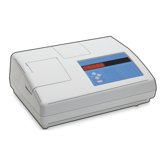
The turbidimeter has a built-in printer and an RS232 output for Figure 2 Back overview connection to a printer, data logger or computer and a recorder output. The turbidimeter contains a real-time clock with battery. The clock provides a time-date stamp on all data transmitted to the built-in printer or to external devices by way of the RS232 interface (i.e., measurements and calibration records). -
Page 11: Installation
4. Push the paper through until the point of the paper comes out the exit slot. ® 1 2100AN IS turbidimeter 6 Gelex secondary turbidity 5. Pull the paper out of the exit slot until the full width of the paper is standardization kit past the exit slot. -
Page 12: User Interface
User interface Table 1 Key descriptions (continued) Description Figure 4 Keypad Starts the changing of the sample number shown on the mode display. Selects automatic or manual ranging. Selects the unit of measure. Exits Calibration or Setup mode without saving changes. Turns Ratio on or off. - Page 13 Table 2 Light descriptions Figure 5 Indicator lights Light Description Illuminated when the instrument light source is on. Flashes when there is not sufficient light for measurement. CAL? "CAL?" is shown during a calibration if the calibration data is not within the acceptable range.
-
Page 14: Startup
Startup Set the date and time Turn the instrument on 1. Push SETUP. The SETUP light turns on. 2. Use the arrow keys to select an option: C A U T I O N Option Description Infrared Light Hazard. The infrared light produced by this instrument can cause eye injury. -
Page 15: Prepare The Stablcal Standards
• Make sure that the standards are at the same ambient temperature as other than StablCal, or user-prepared formazin, may result in less accurate calibrations. The manufacturer cannot guarantee the performance of the instrument the instrument before use. if calibrated with co-polymer styrenedivinylbenzene beads or other suspensions. •... -
Page 16: Stablcal Calibration Procedure
StablCal calibration procedure 1. Push CAL/Zero. 2. Get the < 0.1 NTU 3. Apply a small bead 4. Use the oiling cloth 5. Put the vial in the 6. Push ENTER. vial. Clean the vial with of silicone oil from the to apply the oil equally sample cell holder with The CAL/Zero light... -
Page 17: Stablcal Standards Storage
instrument due to small differences in glass and instrument optical StablCal standards storage systems. • Do not move a StablCal standard to a different container for storage. • Do not keep a Gelex vial in the instrument for more time than is Keep StablCal standards in the plastic case provided with the cover necessary to complete measurement. -
Page 18: Measure The Gelex Secondary Turbidity Standards
7. Push RATIO to turn 8. Put the stray light 9. Read the value 10. Record the value Ratio mode on. standard in the sample when stable. Remove on the white diamond cell holder with the the vial from the space on the vial using triangle on the vial instrument. -
Page 19: Calibration Verification
7. Push RATIO to 8. Put the 0–2 NTU 9. Read the value 10. Record the value 11. Do steps 7–10 for select Ratio on or off. Gelex vial in the sample when stable. Remove on the white diamond the other Gelex vials cell holder with the the vial from the space on the vial using... -
Page 20: Clean The Sample Cell
2. Fully rinse the sample cell many times with distilled or deionized Clean the sample cell water. C A U T I O N 3. Clean the internal and external surfaces of the sample cell and cap with 1:1 hydrochloric acid. 4. -
Page 21: Indexing A Single Sample Cell
Indexing a single sample cell When measuring very low turbidity samples, use a single indexed sample cell or a flow cell for all measurements to get precise and repeatable measurements. As an alternative, optically matched sample cells can be used. Refer to Matching sample cells on page 21. - Page 22 7. Repeat step 6 until 8. Put an orientation the lowest value is mark on the marking shown on the display. band near the top of the sample cell where the lowest value is shown. 20 English...
-
Page 23: Matching Sample Cells
Matching sample cells To decrease the effects that optical differences among sample cells can have on turbidity, transmittance or absorbance measurements, measure samples in matched sample cells. It may not be possible to match all sample cells due to the differences in glass. 1. - Page 24 7. Repeat step 6 until 8. Record the value. 9. Put the second 10. Remove the 11. Repeat step 10 12. Put an orientation the lowest value is Put an orientation mark sample cell in the sample cell, turn it until the value matches mark on the marking shown on the display.
-
Page 25: Prepare Dilution Water
The methods typically used for degassing are: Prepare dilution water Dilution water is used when indexing a sample cell or matching sample • Let the sample stand for several minutes cells and to prepare formazin standards. • Apply a vacuum •... -
Page 26: Apply Heat
1. Fill a clean sample cell with sample. Do not put the cap on the Note: Warming may change the sample turbidity. Measure the sample without warming when possible. sample cell. Measure over-range samples 2. Put of the sample cell into the ultrasonic bath and let it stand until visible bubbles are removed. -
Page 27: Turbidity Measurement
Dilution factor = total volume ÷ sample volume Turbidity measurement Example: Dilution factor = 100 ÷ 20 = 5 W A R N I N G 3. Calculate the actual turbidity: Potential explosion and fire hazard. This instrument is for measuring water based Actual turbidity = measured value ×... -
Page 28: Turbidity Measurement Procedure
• Measure samples immediately to prevent temperature changes and Note: As an alternative, matched sample cells may be used for measurements but do not provide as good of accuracy or precision as a single indexed sample cell or settling. Before a measurement is taken, always make sure that the flow cell. -
Page 29: Absorbance And Transmittance Measurement
7. Read and record the value when stable. Note: To print or send (via RS232) a measurement record, push PRINT. Absorbance and transmittance measurement single sample after setting a zero reference point in one of the two modes. • Use a flow cell for measurements. A flow cell is necessary to get the Measurement notes accuracy and reproducibilty specifications shown in Specifications... -
Page 30: Absorbance And Transmittance Measurement Procedure
Absorbance and transmittance measurement procedure Note: To measure samples with negative absorbance, set the analytical zero using the sample with the greatest absorbance, and measure the sample with the least absorbance. Report the reading as negative absorbance. 1. Push UNITS/Exit 2. -
Page 31: Measurement Techniques
7. After the sample flow stops and the display stabilizes, read and record the value. Note: To print or send (via RS232) a measurement record, push PRINT. Measurement techniques display flashes all 0s when the sample measured is less than the selected range. -
Page 32: Ratio On Or Off
Push SIGNAL AVG to turn signal averaging on or off. The SIGNAL AVG if interferences caused by color or light absorbing particles are not light turns on when signal averaging is on. present. Push ENTER when signal averaging is on to erase data in the signal Using the air purge system averaging buffer and provide an immediate update on the display as The air purge system is used to keep condensation off the external... -
Page 33: Using A Flow Cell
2. Fill the flow cell and tubing with water and make sure that there are Figure 8 Standard shop air no leaks or air bubbles. Note: Air bubbles collect in areas that are not cleaned fully. 3. Clean the exterior surface of the flow cell with a soft, lint-free cloth to remove water spots and fingerprints. -
Page 34: Flow Cell Maintenance
5. Clean the inside and outside of the plastic parts and tubing with Flow cell storage laboratory detergent and warm water. • Install the reservoir cover when the system is not in use to prevent Note: At intervals, replace the tubing as contaminants, including contamination of the system by airborne particles. - Page 35 1. The flow valve opens for the selected fill time. Refer to Select the fill Select the fill time time on page 33. The flow cell fills and removes the previous The fill time is the time interval that the flow valve stays open so that sample from the system.
-
Page 36: Measurement Notes
Measurement notes Before measurement, select the printer to use and the print time interval. Refer to Configure the printer output on page 36. Static or dynamic measurement procedure 1. Push PRINT to turn 2. Install the automated 3. Push FLOW. 4. -
Page 37: Use A Cell Adapter
7. Push ENTER. 8. Push the arrow keys 9. Push ENTER to 10. When 11. Push and hold the to select the open the flow valve and measurements are valve-control switch to The display shows measurement time. start the fill time complete, push FLOW. -
Page 38: Install A Cell Adapter
Install a cell adapter N O T I C E Note: Use the application specific calibration (ASC) ability of the instrument to Do not force the cell adapter out of the instrument as serious damage can provide direct reading of results with cell adapters installed. If the ASC ability is not occur. -
Page 39: Configure The Rs232 Connection
5. Push ENTER. Table 5 RS232 command set (continued) 6. Push SETUP. Command Description Configure the RS232 connection Gets the current time in 24-hour format. To change the time, enter TIM=HH:MM (HH=hour, MM=minutes), then push Enter. 1. Push SETUP. The SETUP light turns on. 2. -
Page 40: Configure The Data Recorder Output
For the best accuracy and long-term data comparability, use formazin Note: The recorder minimum and maximum values are selected independently for stock solution from Hach to make formazin standards. each measurement mode. When the measurement mode changes, the previous settings are automatically used. -
Page 41: Calibration Notes
Table 6 Formazin standard preparation (continued) • Make sure that the standards are at the same ambient temperature as the instrument before use. Standard Step 1 Step 2 Step 3 • Use only the provided silicone oil. This silicone oil has the same refractive index as the vial glass and masks minor glass differences 1000 NTU Add 50 mL of dilution With a TenSette... -
Page 42: Formazin Calibration Procedure
Formazin calibration procedure For the best accuracy, use four matched sample cells or the same sample cell for all measurements during calibration. Refer to Matching sample cells on page 21. 1. Push CAL/Zero. 2. Rinse a clean 3. Clean the sample 4. -
Page 43: Making 4000-Ntu Formazin Stock Solution
The instrument may be calibrated using user-selected values of formazin Preparation of formazin stock solution is temperature and technique sensitive. Use standards. Hach formazin stock solution to get the best instrument performance and analytical standard accuracy. 1. Dissolve 5.000 grams of reagent grade hydrazine sulfate ((NH –H... -
Page 44: Prepare Formazin Standards - User Selected
Calibration with user-selected values of formazin standards is done To change the value on the display during calibration: using the same method that is used to calibrate the instrument with recommended formazin standards with two differences: 1. Push the right arrow key. The decimal point flashes. 2. -
Page 45: Initial Asc Entry
If the display flashes 0s when measuring Absorbance or transmittance, 3. Use the arrow keys to select a measurement units option: set the analytical reference point again and measure again. Also, make Option Description sure that the expected reading is positive when measuring absorbance. Initial ASC entry U SET 0 Sets all the units as available on the display: FNU, FAU, NTU, -1-, -2-, EBC, %T, A... -
Page 46: Replace A Fuse
Troubleshooting Replace a fuse Refer to the tables in this section for error codes, diagnostic codes, D A N G E R common problem messages or symptoms, possible causes and corrective actions. Fire hazard. Use the same type and current rating to replace fuses. Error codes Replacement parts: Table 7... -
Page 47: Diagnostic Codes
Table 7 Error codes (continued) Table 7 Error codes (continued) Error Description Solution Error Description Solution ERR03 Low light error ERR11 System loop test error 1. Put the sample in the instrument again. 1. Turn the instrument off and then back on. 2. -
Page 48: Flashing 9S
To delete any calibration data entered by the user: Replacement parts 1. Turn off the instrument. Description Quantity Item no. 2. Push and hold CAL/Zero. 3. Turn on the instrument. Calibration kit, StablCal ® , sealed sample cells (<0.1, 20, 200, 1000, 4000 and 2659505 The CAL? light flashes. - Page 49 Accessories Accessories (continued) Description Quantity Item no. Description Quantity Item no. Formazin stock solution, 4000 NTU 500 mL 246149 ® Calibration kit, StablCal , 100 mL each 2659510 (<0.1, 20, 200, 1000, 4000 and 7500 NTU) Formazin high-range turbidity standard, 2584202 7500 NTU ampule ®...
- Page 50 Accessories (continued) Description Quantity Item no. Volumetric flask, 100 mL, Class A 1457442 Volumetric flask, 200 mL, Class A 1457445 Optional reagents Description Quantity Item no. Hexamethylenetetramine 500 g 187834 Hydrazine sulfate 100 g 74226 48 English...
- Page 52 Tel. +49 (0) 2 11 52 88-320 SWITZERLAND Fax (970) 669-2932 Fax +49 (0) 2 11 52 88-210 Tel. +41 22 594 6400 orders@hach.com info@hach-lange.de Fax +41 22 594 6499 www.hach.com www.hach-lange.de © Hach Company/Hach Lange GmbH, 2012. All rights reserved. Printed in U.S.A.
Need help?
Do you have a question about the 2100AN IS and is the answer not in the manual?
Questions and answers