Advertisement
Quick Links
Advertisement

Related Manuals for FlySky Paladin Lite


Summary of Contents for FlySky Paladin Lite
- Page 1 L18 EV Lite PL18 Lite Quick Start Guide...
- Page 2 RF signal emissions must be provided to end users and installers. Hereby, [Flysky Technology Co., Ltd.] declares the RF equipment [Paladin lite PL18 lite] to be in accordance with RED2014/53/EU. 3. The full text of the EU DOC is available at: www.flyskytech.
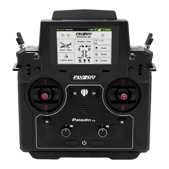
- Page 3 Front View [15] [16] [17] [18] [19] [20] [21] [22] [23] [10] [24] [11] [25] [12] [13] [26] [27] [14] Antenna [13] VRA Knob 320×480 TFT LCD [14] Left Power Button SWF- 2 Position Switch [15] SWD-3 Position Switch SWH-2 Position Switch, Self- SWE-3 Position Switch [16] Resetting...
- Page 4 [37] FRM301 RF Module Gimbal Stiffness Adjustment [30] FRM301 Button [38] Screw Gimbal Stiffness Adjustment [31] [39] Grip Screw Fixed hole of the RF module [32] Grip [40] adapter For more information about the Paladin Lite transmitter please read the user manual.
- Page 5 Powering On Check to make sure that the battery is fully charged; Press both power buttons until the screen turns on. If any switches are not at their highest positions, or the throttle is not at its lowest position, the system will prompt: “Switch is not in the highest position, throttle is not at the lowest...
- Page 6 Main Screen Introduction [11] [12] [13] [14] [15] [16] [10] Model Name TR5 Trim Value Binding Indicate/ Signal [10] Lock/Unlock Strength Sensor [11] Transmitter Power Work Mode [12] Home Page Vioce [13] Function Menu Icon vibration [14] Channel Display TR3 Trim Value [15] TR4 Trim Value Model Type...
- Page 7 Gimbal Adjustment Instructions Function Setup: By adjusting the tension screws on the back of the radio, gimbal stick can be either self-centering or non self-centering. Screw Description Adjusting screw for self- Stick friction adjusting screw centering/non self-centering for non self-centering of the of the right stick right stick Stick friction adjusting screw...
- Page 8 Take right gimbal as example: When the counterclockwise adjustment is made, entire range of movement of the screw Attention is about 3mm. Be cautious not to adjust it too far or the screw will fall out. Non Self-centering to Self-centering Use a Phillips screwdriver to adjust the screw [A ] counterclockwise until the gimbal stick changes to self- centering.
- Page 9 Servo Frequency This function is used to adjust the frequency of the channel output control servo, including analog servo (50 Hz), digital servo (380 Hz) and custom. The correct output frequency value can be selected or set according to the servo used. The system defaults to analog servo and the custom frequency adjustment range is between 50-400 Hz.
- Page 10 Language his transmitter has 2 languages available: Function Setup: Touch the function menu icon to enter the function menu, touch [System], then touch [Language]. Touch your preferred language option and touch the back icon to save and exit. RF Module Update If the following prompt is displayed on start up, the RF module needs to be updated.
- Page 11 Binding The transmitter and receiver have been pre-bound at the factory,however if you need to bind a new receiver or rebind the original receiver follow the steps below. Antenna Power CH10-CH8 CH 1- CH 7 SERVO SENS BIND Connect the bind cable to the receivers bind port. Connect power to any of the receivers other ports.
- Page 12 If after an update the transmitter is unable to connect or bind to the receiver, it is necessary to put the receiver into forced update mode, then go to the RX Setup menu and select RX update as normal. Insert the bind cable as shown to short the pins and enter forced update mode.
- Page 13 Model Type The transmitter includes a variety of options for modes, including fixed wing, glider, helicopter, multi-axis/quad and excavators. Before setting up,a model type must be Attention selected. Function Setup: Touch the function menu icon to enter the function menu, touch [Models], then touch [Set model type]. The currently selected model will be highlighted in green.
- Page 14 Failsafe Function This function protects the user by preventing the model from behaving unexpectedly if signal is lost. All 18 channels are displayed failsafe menu. If set to [OFF], the channel will remain at its last set position before losing signal. If a percentage is displayed, then that channel will move to that percentage when signal is lost.
- Page 15 Specifications Paladin Lite (PL18 Lite) Product Model PL18 Lite Channels 2.4GHz Maximum Power < 20dBm (e.i.r.p.) (EU) 2.4GHz Protocol AFHDS 3 Low Voltage Alarm < 3.65V Data Interface Micro USB Charging Port Micro USB Antenna Built-in Antenna Input Power 1S (3.7V)*4300mAh...
- Page 16 厘米的间隔距离。 必须将天线安装说明和满足射频讯号辐射 的发射机操作条件提供给终端用户和安装人员。 特 此, 【Flysky Technology Co., Ltd.】声 明 无 线 电 设 备 【Paladin Lite(PL18 Lite ), FT18 Lite】 符 合 RED2014/53/EU. 欧 盟 DOC 声 明 全 文 可 在 以 下 互 联 网 地 址: www.
- Page 17 [15] [16] [17] [18] [19] [20] [21] [22] [23] [10] [24] [11] [25] [12] [13] [26] [27] [14] 天线 [15] SWD 三档开关 320*480 显示屏 [16] SWH 二档复位开关 SWF 两档开关 [17] SWG 二档开关 SWE 三档开关 [18] VRE 拨杆 /VRE 旋钮(A/B) SWB 三档开关 [19] TR2 按键...
- Page 18 [31] [39] [32] [40] [28] 蓝牙模块接口 [35] 提手 [29] FRM301 指示灯 [36] 按压弹出 FRM301 [30] FRM301 按键 [37] 高频头模块 FRM301 [31] 总成座松紧度调节 [38] 总成座松紧度调节 [32] 小手胶 [39] 小手胶 [33] Micro USB 接口 [40] 高频头转接件固定孔 [34] 教练接口 关于 Paladin Lite 发射机的更多操作请阅读使用说明书。...
- Page 19 开机 1. 检查系统状态,确保 电池电量充足; 2. 同时按住发射机两个电源 键开机。 开机警告! 当开机语音提示“开关不在 最高位,油门不在最低位” 或“Switch is not in the highest position,throttle is not at the lowest position”,同时发射机弹出提示界面时(红色表示对应控 件位置需调整),请根据提示检查按键,开关,摇杆,并按 照发射机提示将其放在正确位置。 关机 1. 断开接收机电源; 2. 同时长按发射机两个电源键,直至屏幕熄灭,表示关机。 发射机屏幕熄灭后,需等待 3s 后,方可完全关闭,期间 请勿再次开机。 关闭前,请务必先断开接收机电源,然后关闭发射机。 如果强行关闭发射机,将有可能导致遥控设备失控或者 引擎继续工作而引发事故。...
- Page 20 主界面介绍 [11] [12] [13] [14] [15] [16] [10] 模型名称 TR5 微调值 接收机状态 [10] 锁屏键 传感器 [11] 发射机电量 工作模式 [12] 主页栏 声音 [13] 点击可进入功能菜单 振动 [14] 通道显示 TR3 微调值 [15] TR4 微调值 模型类型 [16] TR6 微调值 表示功能或此界面被锁定不 表示此功能或此界面可操作 可操作 表示此功能在禁用状态 表示此功能在开启状态 点击可使功能恢复初始值...
- Page 21 总成座调节说明 功能设置: 用户可调节螺丝孔螺丝实现总成座回中与不回中切换,请参 照以下步骤: 螺丝说明: 右摇杆不回中时摇杆摩擦力调 A 右摇杆回中 / 不回中调节螺丝 B 节螺丝 左摇杆不回中时摇杆摩擦力调 D 左摇杆回中 / 不回中调节螺丝 节螺丝...
- Page 22 以右边摇杆为例: 螺丝总行程约为 6 圈(最紧到最松),逆时针调节时 注意 请不要过调,否则可能导致螺丝脱落。 不回中 - 回中: 1. 请用十字螺丝刀逆时针调节 A 位置螺丝使摇杆变为回中 状态; 2. 逆时针调节 B 位置螺丝调整摩擦力度 ; 回中 - 不回中: 1. 请用十字螺丝刀顺时针调节 A 位置螺丝使摇杆为不回中 状态; 2. 顺时针调节 B 位置螺丝加强摩擦力度;...
- Page 23 舵机响应速度 此功能用于调节通道输出控制舵机频率,该功能包括模拟 舵 机(50Hz)、 数 字 舵 机(380Hz)、 自 定 义 频 率, 可 根据使用的舵机选择或设置正确的输出频率值,系统默认 数字舵机,自定义频率调节范围在 50-400Hz 之间。 功能设置: • 进入主界面,点击 • 进入【接收机设置】,点击【舵机响应速度】 • 点击选择模拟舵机、数字舵机或自定义频率 • 如选择自定义频率,请点击屏幕“+”、“-”进行频 率调节 为了使舵机正常运行,请先查阅舵机使用说明书确 认舵机正确频率,然后通过该功能对舵机频率数值 进行更改。...
- Page 24 语言 本发射机可使用两种语言: 功能设置: 点击主界面 图标,进入功能菜单界面,选择进入 [ 系 统设置 ] 功能,点击 [ 语言选择 ], 进入设置界面,可根据 需要选择语言, 设置完成后, 点击返回 , 保存设置并退出。 高频模块固件升级 当开机时弹出如下提示,则需要更新高频模块。 点击“是”,进入更新状态,点击“否”,退出更新界面, 此时如需升级高频头,请参照以下步骤: 更新步骤: 点击主界面 图标,进入功能菜单界面,选择进入 [ 高 频设置 ] 功能,点击 [ 高频模块固件升级 ], 在弹出提示后, 点击 [ 是 ],更新完成后,自动退出更新界面。...
- Page 25 时,请按照如下步骤进行对码: 电源 天线 CH10-CH8 CH 1- CH 7 SERVO SENS BIND 发射机在更新完后,如无法与接 插入对码 线短接 , 收机对码,需强制更新接收机。 可以进入 在接收机进入强制更新模式后, 强制更新 在 [ 接收机设置 ] 功能中选择 [ 接 模式 收机固件更新 ],选择对应的接收机后点击 [ 升级 ],即 可完成更新。 以上步骤适用于 Paladin Lite 与 FTr10 的接收机对码,如 您使用的是其他接收机,请进入官网查询。...
- Page 26 模型类型 此发射机包含飞机模式、滑翔机模式、直升机模式、多 轴、工程车等多种模型。 在设置各模型结构前,必须先选择正确的模型类型。 功能设置: 点击主界面 图标, 进入功能菜单界面, 选择进入 [ 模 型 ] 功能中 [ 设置模型类型 ]; 绿色高亮状态的模型表示发射机当前模型类型。 如需切换模型类型,点击对应模型图标,在弹出的提 示框中点击 [ 是 ],设置成功后将进入对应模型的结构 设置界面。 设置完成后点击此图标 ,即可退出 。...
- Page 27 失控保护 该功能用于在接收机丢失信号或失控后,保护模型和操作 人员的安全。 失控保护菜单下显示 18 个通道的列表,如果在通道后显示 [ 关闭 ],表示失控后,该通道输出最后通道值。如果显示 一个百分比,则表示失控后,该通道输出此固定值。 触发时间:可设置失控生效的时间。 功能设置: 点击主界面 图标,进入功能菜单界面,选择进入 [ 接 收机设置 ] 功能,点击 [ 失控保护 ], 进入设置界面,可根 据需要进行失控保护的设置。 保护值设置方法: 点击选择所需设置通道, 将通道对应控件 (摇杆、 按键、 开关、 滑杆)移动至所需位置保持不动,点击返回 ,保存设置 并退出。 当对应通道界面显示 图标时,表示该功能处于关闭 状态,设置无效。 失控保护功能需进入 [ 辅助通道 ] 功能为通道分配控件 后,方可进行对应通道的失控保护设置。...
- Page 28 规格参数 Paladin Lite (PL18 Lite) 产品型号 PL18 Lite 通道个数 无线频率 2.4GHz ISM 发射功率 < 20dBm (EU) 无线协议 AFHDS 3 低电压报警 < 3.65 V 数据接口 Micro USB 充电接口 Micro USB 天线类型 内置天线 输入电源 1S (3.7V)*4300mAh 在线更新 支持 外形尺寸 196*214*86.5mm 895g(A 版)...
- Page 29 FCC ID: N4ZFT1800 出版日期 :2023-12-21 Copyright ©2023 Flysky Technology Co., Ltd.
Need help?
Do you have a question about the Paladin Lite and is the answer not in the manual?
Questions and answers