Table of Contents
Advertisement
Quick Links
Advertisement
Table of Contents

Subscribe to Our Youtube Channel
Related Manuals for NI NI-9147


Summary of Contents for NI NI-9147
- Page 1 NI-9147 Getting Started 2024-01-30...
-
Page 2: Table Of Contents
Mounting the NI-9147 Directly on a Flat Surface....... . 19... - Page 3 Installing Software on the NI-9147........
-
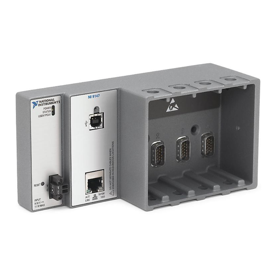
Page 4: Ni-9147 Features
4. Power Connector 5. RESET Button RJ-45 Gigabit Ethernet Port The NI-9147 has one tri-speed RJ-45 Gigabit Ethernet port. By default, the Ethernet port is enabled and configured to obtain an IP address automatically. The Ethernet port can be configured in MAX. -
Page 5: Power Connector
151733-05 10 m 151733-10 Power Connector The NI-9147 has a power connector to which you can connect a power supply. The following table shows the pinout for the power connector. Table 3. Power Connector Pinout Pinout Description Power input Common The NI-9147 has reverse-voltage protection. -
Page 6: Usb Device Port
20 A, 85-276 VAC Input USB Device Port The NI-9147 USB device port is intended for device configuration, application deployment, debugging, and maintenance. For example, you can use the USB device port to install software or driver updates during field maintenance instead of interrupting communication on the RJ-45 Ethernet ports. -
Page 7: Chassis Grounding Screw
The NI-9147 provides a chassis grounding screw. Figure 2. NI-9147 Chassis Grounding Screw 1. Chassis grounding screw For EMC compliance, you must connect the NI-9147 to earth ground through the chassis ground screw. Use wire that is 2.1 mm (14 AWG) solid copper wire with a maximum length of 1.5 m (5 ft). -
Page 8: Internal Real-Time Clock
The NI-9147 contains a lithium cell battery that stores the system clock information when the NI-9147 is powered off. There is only a slight drain on the battery when power is applied to the NI-9147 power connector. The rate at which the battery drains when power is disconnected depends on the ambient storage temperature. -
Page 9: Buttons
Buttons The NI-9147 provides the following buttons. 1. RESET Button System Reset The following figure shows the reset behavior of the NI-9147. Figure 3. Reset Button Behavior Press and hold RESET button for < 5 s Press and hold RESET button for ≥ 5 s •... -
Page 10: Leds
NI-9147 Getting Started LEDs The NI-9147 provides the following LEDs. 1. POWER LED 2. STATUS LED 3. USER FPGA1 LED 4. RJ-45 Ethernet LEDs POWER LED Indicators The following table lists the POWER LED indicators. Table 6. POWER LED Indicators... - Page 11 Table 7. STATUS LED Indicators LED Pattern Indication Blinks twice and pauses The NI-9147 is in safe mode. Software is not installed, which is the factory default state, or software has been improperly installed on the NI-9147. An error can occur when an attempt to upgrade the software is interrupted.
- Page 12 NI-9147 Getting Started User LED You can define the USER FPGA1 LED to meet the needs of your application. The following table lists the USER FPGA1 LED indicators. Table 8. User LEDs LED Color Description USER FPGA1 Green/Yellow Use the LabVIEW FPGA Module...
-
Page 13: Ni-9147 Block Diagram
NI-9147 Getting Started NI-9147 Block Diagram RJ-45 GigE 512 MB Xilinx Zynq-7000 Ethernet1 MAC/PHY NAND Flash XC7Z020 All-Programmable SOC 256 MB USB 2.0 Device Port DDR3 Hardware Data NI 9147 © National Instruments... -
Page 14: Unpacking The Kit
3. Unpack any other items and documentation from the kit. Store the device in the antistatic package when the device is not in use. Verifying the Kit Contents Verify that the following items are included in the NI-9147 kit. NI-9147 ■... -
Page 15: Installing Software On The Host Computer
NI-9147 Getting Started Installing Software on the Host Computer Before using the NI-9147, you must install the following application software and device drivers on the host computer in this order: 1. LabVIEW 2014 SP1 or later 2. LabVIEW FPGA Module 2014 SP1 or later 3. -
Page 16: Mounting The Ni-9147
You can also mount the NI-9147 in other orientations, on a nonmetallic surface, on a 35-mm DIN rail, on a desktop, or in a rack. Mounting the NI-9147 in these or other configurations can reduce the maximum allowable ambient temperature and can affect the typical accuracy of modules in the NI-9147. -
Page 17: Mounting Requirements
Mounting Requirements Your installation must meet the following requirements for cooling and cabling clearance. Allow 25.4 mm (1.00 in.) on the top and the bottom of the NI-9147 for air circulation, as shown in the following figure. © National Instruments... -
Page 18: Ambient Temperature
(1.14 in.) Ambient Temperature Measure the ambient temperature at each side of the NI-9147, 63.5 mm (2.50 in.) from the side and 25.4 mm (1.00 in.) forward from the rear of the NI-9147, as shown in the following figure. ni.com... -
Page 19: Mounting The Ni-9147 Directly On A Flat Surface
1. Location for measuring the ambient temperature Mounting the NI-9147 Directly on a Flat Surface For environments with high shock and vibration, NI recommends mounting the NI-9147 directly on a flat, rigid surface using the mounting holes in the NI-9147. What to Use NI-9147 ■... -
Page 20: Surface Mounting Dimensions
30.6 mm (1.86 in.) (1.20 in.) 47.0 mm (1.85 in.) 41.1 mm (1.62 in.) 4.1 mm (0.16 in.) Mounting the NI-9147 on a Panel You can use the NI panel mounting kit to mount the NI-9147 on a panel. ni.com... - Page 21 Complete the following steps to mount the NI-9147 on a panel. 1. Align the NI-9147 and the panel mounting plate. 2. Fasten the panel mounting plate to the NI-9147 using the screwdriver and M5 or number 10 screws. NI provides these screws with the panel mounting kit.
-
Page 22: Panel Mounting Dimensions
(1.25 in.) (3.47 in.) 63.5 mm (2.50 in.) Mounting the NI-9147 on a DIN Rail You can use the NI DIN rail mounting kit to mount the NI-9147 on a standard 35-mm DIN rail. What to Use NI-9147 ■ Screwdriver, Phillips #2 ■... -
Page 23: Clipping The Device On A Din Rail
NI-9147 Getting Started 1. Align the NI-9147 and the DIN rail clip. 2. Fasten the DIN rail kit to the NI-9147 using the screwdriver and M4 × 25 flathead screws. NI provides these screws with the DIN rail mounting kit. -
Page 24: Mounting The Controller On A Rack
DIN rail. Mounting the Controller on a Rack You can use the following rack mount kits to mount the NI-9147 and other DIN rail- mountable equipment on a standard 482.6 mm (19 in.) rack. NI Sliding Rack-Mounting Kit, 779102-01 ■... -
Page 25: Installing C Series Modules
Figure 12. Installing C Series Modules 1. Verify that power is not connected to the I/O connector(s) on the C Series module. If the system is in a nonhazardous location, the NI-9147 can be powered on when you install modules. -
Page 26: Removing C Series Modules
Verify that power is not connected to the I/O connector(s) on the C Series module before you remove a module from the NI-9147. If the system is in a nonhazardous location, the NI-9147 can be powered on when you remove modules. -
Page 27: Connecting The Ni-9147 To Ground
Complete the following steps to ground the NI-9147. 1. Attach the ring lug to the wire. 2. Remove the grounding screw from the grounding terminal on the NI-9147. 3. Attach the ring lug to the grounding terminal. 4. Tighten the grounding screw to 0.5 N · m (4.4 lb · in.) of torque. -
Page 28: Connecting The Ni-9147 To Power
NI-9147 Getting Started Connecting the NI-9147 to Power The NI-9147 requires a 9 V to 30 V external power supply. The NI-9147 filters and regulates the supplied power and provides power for the C Series modules. The NI-9147 has one layer of reverse-voltage protection. -
Page 29: Powering On The Ni-9147
7. Power on the power supply. Powering On the NI-9147 When you power on the NI-9147 for the first time, the device boots into safe mode. The POWER LED illuminates, the STATUS LED illuminates briefly, and then the STATUS LED blinks twice every few seconds. -
Page 30: Connecting The Ni-9147 To The Host Computer Or Network
NI-9147 Getting Started Connecting the NI-9147 to the Host Computer or Network You can connect the NI-9147 to the host computer and/or network in the following ways: USB device port ■ RJ-45 Ethernet port ■ NI recommends using the USB device port for configuration, debug, and maintenance. -
Page 31: Finding The Ni-9147 On The Network (Dhcp)
NI-cRIO-9147-1856AAA. Connecting the NI-9147 to the Host Computer Using the USB Device Port Complete the following steps to connect the NI-9147 to the host computer using the USB device port. 1. Power on the host computer. -
Page 32: What To Do When The Ni-9147 Is Not Communicating With The Network
■ steps. 1. Use a USB A-to-B cable to connect the NI-9147 USB device port to a host computer. The USB driver creates a virtual network interface card and assigns an IP address to the NI-9147 in the format of 172.22.11.x. -
Page 33: Verify The System Ip Configuration
2. Set a new DHCP connection by holding the RESET button down for 5 seconds. The STATUS LED repeats the same behavior from Step If the NI-9147 fails to set a new DHCP address, it assigns itself a link-local IP address. If the DHCP connection is successful and appropriate for your application, skip to Step 3. - Page 34 NI-9147 Getting Started Ensure that UDP port 44525 is open to communication on the host ■ computer. If you are using an intelligent switch on the network, ensure that it is not disabling UDP port 44525. ni.com...
-
Page 35: Configuring The System In Measurement & Automation Explorer (Max)
Complete the following steps to set a system password. Note The default username for the NI-9147 is admin. There is no default password for the NI-9147, so you must leave the password field blank when logging in until you set a system password. -
Page 36: Installing Software On The Ni-9147
6. Click Next. 7. Select NI Scan Engine from the software add-ons. Select any additional software to install. If you plan on using the NI-9147 with the LabVIEW FPGA Module, you can click Next. Click NI Scan Engine if you plan on using the NI-9147 without the LabVIEW FPGA Module. -
Page 37: Configuring Startup Options
You can configure the startup options using the USB device port or the RJ-45 Gigabit Ethernet port 1 or port 2. Complete the following steps to configure the NI-9147 startup options in MAX. 1. In MAX, expand your system under Remote Systems. - Page 38 Enable Secure Shell (SSH) Logins Rebooting the NI-9147 with this setting on starts sshd on the NI-9147. Starting sshd enables logins over SSH, an encrypted communication protocol.
Need help?
Do you have a question about the NI-9147 and is the answer not in the manual?
Questions and answers