
Related Manuals for NI PXIe-1082DC


Summary of Contents for NI PXIe-1082DC
- Page 1 PXI Express NI PXIe-1082DC User Manual NI PXIe-1082DC User Manual July 2014 373876C-01...
- Page 2 Worldwide Technical Support and Product Information ni.com Worldwide Offices Visit ni.com/niglobal to access the branch office websites, which provide up-to-date contact information, support phone numbers, email addresses, and current events. National Instruments Corporate Headquarters 11500 North Mopac Expressway Austin, Texas 78759-3504 USA Tel: 512 683 0100...
- Page 3 You must obtain an RMA number from NI before returning any product to NI. NI reserves the right to charge a fee for examining and testing Hardware not covered by the Limited Warranty.
- Page 4 LEAD TO DEATH, PERSONAL INJURY, SEVERE PROPERTY DAMAGE OR ENVIRONMENTAL HARM (COLLECTIVELY, “HIGH-RISK USES”). FURTHER, PRUDENT STEPS MUST BE TAKEN TO PROTECT AGAINST FAILURES, INCLUDING PROVIDING BACK-UP AND SHUT-DOWN MECHANISMS. NI EXPRESSLY DISCLAIMS ANY EXPRESS OR IMPLIED WARRANTY OF FITNESS OF THE PRODUCTS OR SERVICES FOR HIGH-RISK...
- Page 5 The Declaration of Conformity (DoC) contains important EMC compliance information and instructions for the user or installer. To obtain the DoC for this product, visit , search by ni.com/certification model number or product line, and click the appropriate link in the Certification column.
-
Page 6: Table Of Contents
Key Features ........................1-1 Chassis Description ......................1-3 Optional Equipment......................1-4 Rack Mount Kit ......................1-4 NI PXIe-1082DC Chassis Backplane Overview .............. 1-5 Interoperability with CompactPCI................1-5 System Controller Slot....................1-6 Hybrid Peripheral Slots .................... 1-6 PXI Express Peripheral Slots..................1-6 System Timing Slot .................... - Page 7 Installation ........................ 3-3 Configuration ......................3-3 Connecting to Power Source..................3-3 Appendix A Specifications Appendix B Pinouts System Controller Slot Pinouts..................B-1 System Timing Slot Pinouts ..................... B-4 Hybrid Slot Pinouts......................B-6 Appendix C NI Services Glossary Index viii | ni.com...
-
Page 8: About This Manual
About This Manual The NI PXIe-1082DC User Manual describes the features of the NI PXIe-1082DC chassis and contains information about configuring the chassis, installing the modules, and operating the chassis. Related Documentation The following documents contain information that you might find helpful as you read this manual: •... -
Page 9: Getting Started
Getting Started This chapter describes the key features of the NI PXIe-1082DC chassis and lists the kit contents and optional equipment you can order from National Instruments. Unpacking Carefully inspect the shipping container and the chassis for damage. Check for visible damage to the metal work. - Page 10 Chapter 1 Getting Started The key features of the NI PXIe-1082DC chassis include the following: • High Performance for Instrumentation Requirements – Up to 1 GB/s (single direction) per PXI Express slot dedicated bandwidth (x4 PCIe) – 38 W per slot cooling meets increased PXIe cooling requirements –...
-
Page 11: Chassis Description
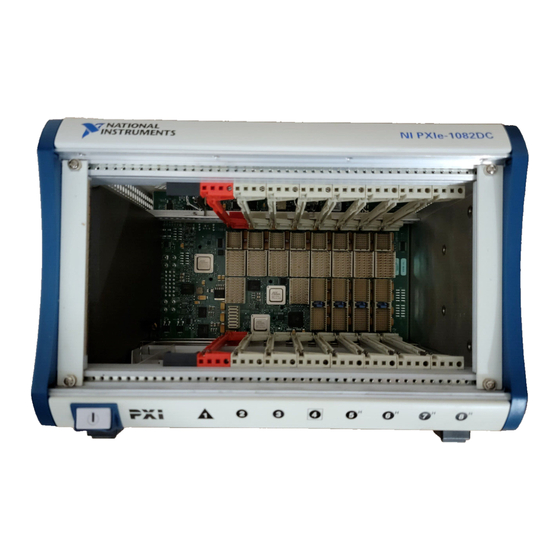
Chassis Description Figures 1-1 and 1-2 show the key features of the NI PXIe-1082DC chassis front and back panels. Figure 1-1 shows the front view of the NI PXIe-1082DC. Figure 1-2 shows the rear view of the NI PXIe-1082DC. Figure 1-1. Front View of the NI PXIe-1082DC Chassis... -
Page 12: Optional Equipment
Contact National Instruments to order the following option for the NI PXIe-1082DC chassis. Rack Mount Kit There are two optional kits for mounting the NI PXIe-1082DC chassis into a rack. The first option is a pair of mounting brackets for use on the front of the chassis. The second option is a rear rack mount kit. -
Page 13: Ni Pxie-1082Dc Chassis Backplane Overview
NI PXIe-1082DC Chassis Backplane Overview This section provides an overview of the backplane features for the NI PXIe-1082DC chassis. Interoperability with CompactPCI The design of the NI PXIe-1082DC provides you the flexibility to use the following devices in a single PXI Express chassis: •... -
Page 14: System Controller Slot
There are two PXI Express peripheral slots: slot 2 and slot 3. PXI Express peripheral slots accept the following modules: • A PXI Express Peripheral with x4 or x1 PCI Express link to the system slot • A CompactPCI Express Type-2 Peripheral with x4 or x1 PCI Express link to the system slot 1-6 | ni.com... -
Page 15: System Timing Slot
NI PXIe-1082DC User Manual System Timing Slot The System Timing Slot is slot 4. The system timing slot will accept the following peripheral modules: • A PXI Express System Timing Module with x4 or x1 PCI Express link to the system slot. -
Page 16: Pxi Local Bus
1 is not routed anywhere. The right Local Bus 6 from slot 8 is also not routed anywhere. Local bus signals may range from high-speed TTL signals to analog signals as high as 42 V. Initialization software uses the configuration information specific to each adjacent peripheral module to evaluate local bus compatibility. 1-8 | ni.com... -
Page 17: Pxi Trigger Bus
System Reference Clock The NI PXIe-1082DC chassis supplies PXI_CLK10, PXIe_CLK100, and PXIe_SYNC100 to every peripheral slot with an independent driver for each signal. An independent buffer (having a source impedance matched to the backplane and a skew of less than 500 ps between slots) drives PXI_CLK10 to each peripheral slot. - Page 18 10 MHz REF IN PXIe_CLK100 and PXIe_SYNC100 No clock present No clock present Backplane generates its own clocks No clock present 10 MHz clock present PXI_CLK10, PXIe_CLK100 and PXIe_SYNC100 all phase-locked to Rear Chassis Panel—10 MHz REF IN 1-10 | ni.com...
-
Page 19: Pxie_Sync_Ctrl
NI PXIe-1082DC User Manual Table 1-1. Backplane External Clock Input Truth Table (Continued) System Timing Slot Rear Chassis Panel Backplane PXI_CLK10, PXI_CLK10_IN 10 MHz REF IN PXIe_CLK100 and PXIe_SYNC100 10 MHz clock present No clock present PXI_CLK10, PXIe_CLK100 and PXIe_SYNC100 all phase-locked to System Timing Slot—PXI_CLK10_IN... -
Page 20: Installation And Configuration
Installation and Configuration This chapter describes how to prepare and operate the NI PXIe-1082DC chassis. Before connecting the chassis to a power source, read this chapter and the Read Me First: Safety and Electromagnetic Compatibility document included with your kit. -
Page 21: Chassis Cooling Considerations
Installation and Configuration Chassis Cooling Considerations The NI PXIe-1082DC chassis is designed to operate on a bench or in an instrument rack. The chassis must be oriented horizontally for benchtop use. Vertical orientation with the chassis handle up is not a supported configuration. Regardless of the configuration you must provide the cooling clearances as outlined in the following sections. -
Page 22: Chassis Ambient Temperature Definition
Power Inhibit Switch LED Indicator section of this chapter. Setting Fan Speed The fan-speed selector switch is on the rear panel of the NI PXIe-1082DC chassis. Refer to Figure 1-2, Rear View of the NI PXIe-1082DC Chassis, to locate the fan-speed selector switch. -
Page 23: Connecting Safety Ground
Installing a PXI Express System Controller This section contains general installation instructions for installing a PXI Express system controller in a NI PXIe-1082DC chassis. Refer to your PXI Express system controller user manual for specific instructions and warnings. To install a system controller, complete the... - Page 24 Figure 2-4 shows a PXI Express system controller installed in the system controller slot of a NI PXIe-1082DC chassis. You can place CompactPCI, CompactPCI Express, PXI, or PXI Express modules in other slots depending on the slot type.
-
Page 25: Installing Peripheral Modules
Started, for a description of the various slot types. This section contains general installation instructions for installing a peripheral module in a NI PXIe-1082DC chassis. Refer to your peripheral module user manual for specific instructions and warnings. To install a module, complete the following steps: Inspect the slot pins on the chassis backplane for any bending or damage prior to installation. - Page 26 NI PXIe-1082DC User Manual Ensure that the chassis is powered off. Install a module into a chassis slot by first placing the module card PCB into the front of the card guides (top and bottom), as shown in Figure 2-5. Slide the module to the rear of the chassis, making sure that the injector/ejector handle is pushed down as shown in Figure 2-5.
-
Page 27: Power Inhibit Switch Led Indicator
Remote Voltage Monitoring and Control The NI PXIe-1082DC chassis supports remote voltage monitoring and inhibiting through a female 9-pin D-SUB (DB-9) connector located on the rear panel. Table 2-1 shows the pinout of the 9-pin D-SUB (DB-9) connector. - Page 28 (DB-9) connector, be careful not to short the probe leads together. Doing so could damage the power supply. You can use a digital voltmeter to ensure all voltage levels in the NI PXIe-1082DC chassis are within the allowable limits. Referring to Table 2-2, connect one lead of the voltmeter to a supply pin on the remote voltage monitoring connector (9-pin D-SUB) on the rear panel.
-
Page 29: Inhibit Mode Switch
Inhibit Mode switch must be in the Manual position. PXI_CLK10 Rear Connectors There are two BNC connectors on the rear of the NI PXIe-1082DC chassis for PXI_CLK10. The connectors are labeled IN and OUT. You can use them for supplying the backplane with PXI_CLK10 or routing the backplane’s PXI_CLK10 to another chassis. -
Page 30: Pxi-1 System Configuration
Identify As submenu. Further expanding the PXI System branch shows all devices in the system that can be recognized by NI-VISA. When your system controller and all your chassis are identified, the required file is complete. -
Page 31: Using System Configuration And Initialization Files
System controllers from NI provide the pxisys.ini file for the NI PXIe-1082DC chassis, so you should not need to use the pxisys.ini file. Refer to the documentation provided with the system controller or to chassis.ini for more information on files. -
Page 32: Service Interval
Maintenance This chapter describes basic maintenance procedures you can perform on the NI PXIe-1082DC chassis. Disconnect the power cable prior to servicing a NI PXIe-1082DC chassis. Caution Service Interval Clean dust from the chassis exterior (and interior) as needed, based on the operating environment. -
Page 33: Exterior Cleaning
Avoid chemicals that contain benzene, toluene, xylene, acetone, or similar solvents. Resetting the DC Mains Circuit Breaker If the NI PXIe-1082DC chassis is connected to a DC source and encounters an over-current condition, the circuit breaker on the rear panel will trip to prevent damage to the chassis. -
Page 34: Replacing The Modular Power Supply
Me First: Safety and Electromagnetic Compatibility document included with the kit. Removal The NI PXIe-1082DC power supply is a replacement part for the NI PXIe-1082DC chassis. Before attempting to replace the power supply shuttle, verify that there is adequate clearance behind the chassis. -
Page 35: Appendix A Specifications
Use the DC power cable provided with DC power supplies for VDC input. Caution Using the NI PXIe-1082DC in a manner not described in this document Caution may impair the protection the NI PXIe-1082DC provides. © National Instruments | A-1... - Page 36 System Timing Slot — — — Hybrid Peripheral Slot with — PXI-1 Peripheral Hybrid Peripheral Slot with — — — PXI-5 Peripheral Load regulation Voltage Load Regulation +3.3 V <5% +12 V <5% +5 V <5% -12 V <5% A-2 | ni.com...
- Page 37 NI PXIe-1082DC User Manual Maximum ripple and noise (20 MHz bandwidth) Voltage Maximum Ripple and Noise +3.3 V 50 mV +12 V 120 mV +5 V 50 mV -12 V 50 mV Over-current protection ........All outputs protected from short circuit and...
- Page 38 Sound Pressure Level (at Operator Position) Auto fan (up to ~30 °C ambient) ......48.7 dBA High fan ............61.6 dBA Sound Power Auto fan (up to ~30 °C ambient) ......57.7 dBA High fan ............72.5 dBA Specifications are subject to change without notice. Note A-4 | ni.com...
- Page 39 NI PXIe-1082DC User Manual Safety This product is designed to meet the requirements of the following standards of safety for electrical equipment for measurement, control, and laboratory use: • IEC 61010-1, EN 61010-1 • UL 61010-1, CSA 61010-1 For UL and other safety certifications, refer to the product label or the...
- Page 40 . This page contains the environmental regulations and ni.com/environment directives with which NI complies, as well as other environmental information not included in this document. Waste Electrical and Electronic Equipment (WEEE) At the end of their life cycle, all products must be sent to a WEEE EU Customers recycling center.
- Page 41 NI PXIe-1082DC User Manual Duty-factor............45%-55% Unloaded signal swing........3.3 V ±0.3 V For other specifications refer to the PXI-1 Hardware Specification. Note 100 MHz System Reference Clock: PXIe_CLK100 and PXIe-SYNC100 Maximum slot-to-slot skew ......100 ps Accuracy ............±25 ppm max (guaranteed over the operating temperature range) Maximum jitter ..........
- Page 42 For PXIe slot to PXI_DSTAR mapping refer to the System Timing Slot Notes section of Chapter 1, Getting Started. For other specifications, the NI PXIe-1082DC complies with the PXI-5 PXI Express Hardware Specification. Mechanical Overall dimensions Standard chassis Height..........6.97 in. (177.1 mm) Width..........10.68 in.
- Page 43 Chromate Zinc Plating on Cold Rolled Steel Polyurethane Enamel Figures A-1 and A-2 show the NI PXIe-1082DC chassis dimensions. The holes shown are for the installation of the optional rack mount kits. You can install those kits on the front or rear of the chassis, depending on which end of the chassis you want to face toward the front of the instrument cabinet.
- Page 44 Appendix A Specifications Figure A-2. NI PXIe-1082DC Chassis Dimensions (Bottom) 1.01 in. 12.700 in. (322.58 mm) (25.7 mm) 1.02 in. (25.8 mm) 8.650 in. (219.7 mm) A-10 | ni.com...
- Page 45 NI PXIe-1082DC User Manual Figure A-3 shows the chassis rack mount kit components. Figure A-3. NI Chassis Rack Mount Kit Components Front Rack Mount Kit NI Chassis Optional Rear Rack Mount Kit The chassis shown in Figure A-3 is representative of the Note NI PXI-1042/NI PXIe-1062Q/NI PXIe-1082DC product lines.
-
Page 46: Appendix B Pinouts
Pinouts This appendix describes the connector pinouts for the NI PXIe-1082DC chassis backplane. Table B-1 shows the XP1 Connector Pinout for the System Controller slot. Table B-2 shows the XP2 Connector Pinout for the System Controller slot. Table B-3 shows the XP3 Connector Pinout for the System Controller slot. - Page 47 3PER 3PER 3PER 4PET 4PET 4PER 4PER 4PET 4PET 4PET 4PET 4PER 4PER 4PER 4PER 4PET 4PET 4PER 4PER Table B-3. XP3 Connector Pinout for the System Controller Slot PWR_ PS_O LINK PWRB 4RefCl 4RefCl 2RefCl 2RefCl B-2 | ni.com...
- Page 48 NI PXIe-1082DC User Manual Table B-3. XP3 Connector Pinout for the System Controller Slot (Continued) 3RefCl 3RefCl 1RefCl 1RefCl 1PET 1PET 1PER 1PER 1PET 1PET 1PET 1PET 1PER 1PER 1PER 1PER 1PET 1PET 1PER 1PER 2PET 2PET 2PET 2PET 2PER...
-
Page 49: System Timing Slot Pinouts
A10– PXIe_ PXIe_ PXI_ PXIe_ PXIe_ DSTAR DSTAR STAR6 DSTAR DSTAR B2– B10+ B10– PXIe_ PXIe_ PXIe_ PXIe_ DSTAR DSTAR DSTAR DSTAR A2– C11+ C11– PXIe_ PXIe_ DSTAR DSTAR A11+ A11– PXIe_ PXIe_ DSTAR DSTAR B11+ B11– B-4 | ni.com... - Page 50 NI PXIe-1082DC User Manual Table B-6. XP3 Connector Pinout for the System Timing Slot PXIe_ PXIe_ PXIe_ PXIe_ PXIe_ PXIe_ CLK1 CLK1 SYNC1 SYNC1 DSTAR DSTA PRSN PWRE PXIe_ PXIe_ PXIe_ PXIe_ DSTAR DSTAR DSTAR DSTA SMBD SMBC PERS 1Ref...
-
Page 51: Hybrid Slot Pinouts
3.3V AD[1] V(I/O) AD[0] ACK64# 3.3V AD[4] AD[3] AD[2] AD[7] 3.3V AD[6] AD[5] 3.3V AD[9] AD[8] M66EN C/BE[0]# AD[12] V(I/O) AD[11] AD[10] 3.3V AD[15] AD[14] AD[13] SERR# 3.3V C/BE[1]# 3.3V IPMB_SCL IPMB_SDA PERR# DEVSEL# V(I/O) STOP# LOCK# B-6 | ni.com... - Page 52 NI PXIe-1082DC User Manual Table B-8. P1 Connector Pinout for the Hybrid Slot (Continued) 3.3V FRAME# IRDY# BD_SEL# TRDY# 12– Key Area AD[18] AD[17] AD[16] C/BE[2]# AD[21] 3.3V AD[20] AD[19] C/BE[3]# IDSEL AD[23] AD[22] AD[26] V(I/O) AD[25] AD[24] AD[30] AD[29]...
- Page 53 1PERp6 1PERn6 1PETp7 1PETn7 1PERp7 1PERn7 Table B-10. XP4 Connector Pinout for the Hybrid Slot 5Vaux SYSEN# WAKE# ALERT# 3.3V 3.3V 3.3V PXI_ PXI_ PXI_ PXI_ TRIG3 TRIG4 TRIG5 TRIG6 PXI_ ATNLED PXI_ PXI_ TRIG2 STAR CLK10 B-8 | ni.com...
- Page 54 NI PXIe-1082DC User Manual Table B-10. XP4 Connector Pinout for the Hybrid Slot (Continued) PXI_ PXI_ ATNSW# PXI_ TRIG1 TRIG0 TRIG7 PXI_ PXI_ LBL6 LBR6 © National Instruments | B-9...
-
Page 55: Ni Services
– Warranty and Repair—All NI hardware features a one-year standard warranty that is extendable up to five years. NI offers repair services performed in a timely manner by highly trained factory technicians using only original parts at a National Instruments service center. - Page 56 KnowledgeBase, product manuals, step-by-step troubleshooting wizards, thousands of example programs, tutorials, application notes, instrument drivers, and so on. Registered users also receive access to the NI Discussion Forums . NI Applications Engineers make sure every question submitted ni.com/forums...
-
Page 57: Glossary
Glossary Symbol Prefix Value pico nano μ micro milli kilo mega giga tera Symbols ° Degrees. ≥ Equal or greater than. ≤ Equal or less than. Percent. Amperes. Alternating current. ANSI American National Standards Institute. Auto Automatic fan speed control. American Wire Gauge. - Page 58 A method of propagating signals along a bus, in which the devices are prioritized on the basis of their position on the bus. DB-9 A 9-pin D-SUB connector. Direct current. Declaration of Conformity. D-SUB Subminiature D connector. G-2 | ni.com...
- Page 59 NI PXIe-1082DC User Manual efficiency Ratio of output power to input power, expressed as a percentage. Electronic Industries Association. Electromagnetic Compatibility. Electromagnetic Interference. Federal Communications Commission. filler panel A blank module front panel used to fill empty slots in the chassis.
- Page 60 Meters. Megahertz. One million Hertz; one Hertz equals one cycle per second. Miles. Milliseconds. MTBF Mean time between failure. MTTR Mean time to repair. G-4 | ni.com...
- Page 61 NI PXIe-1082DC User Manual NEMA National Electrical Manufacturers Association. National Instruments. power supply shuttle A removable module that contains the chassis power supply. PCI eXtensions for Instrumentation. PXI_CLK10 10 MHz PXI system reference clock. Relative humidity. Root mean square. Seconds.
- Page 62 The PXI backplane specification defines implementation guidelines for PXI_CLK10. System Timing slot This slot is located at slot 4 and has dedicated trigger lines to other slots. Transistor-transistor logic. Underwriter’s Laboratories. Volts. Volts alternating current. Peak-to-peak voltage. Watts. G-6 | ni.com...
-
Page 63: Index
2-10 figure, 2-2 installation, configuration, and operation CLK10 rear connectors, 2-10 chassis initialization file, 2-12 CompactPCI, interoperability with NI configuration in MAX (figure), 2-11 PXIe-1082DC backplane, 1-5 connecting safety ground, 2-4 configuration in MAX (figure), 2-11 installing a PXI Express system configuration. - Page 64 (figure), 1-4 PXI Express configuration in MAX, 2-10 safety ground, connecting, 2-4 PXI Express peripheral slots, description, 1-6 unpacking, 1-1 PXI Express system controller, 2-4 figure, 2-5 installing in a NI PXIe-1082DC chassis (figure), 2-6 I-2 | ni.com...
- Page 65 100 MHz system reference clock (PXIe_CLK100 and testing power up, 2-4 PXIe_SYNC100), A-7 trigger bus, 1-9 CE compliance, A-5 chassis cooling, A-3 dimensions (figure), A-9, A-10 electrical unpacking the NI PXIe-1082DC chassis, 1-1 DC input, A-1 DC output, A-2 © National Instruments | I-3...
- Page 66 Index voltage monitoring connector. See DB-9 connector voltages at voltage monitoring connector (DB-9) (table), 2-9 WEEE information, A-6 I-4 | ni.com...
Need help?
Do you have a question about the PXIe-1082DC and is the answer not in the manual?
Questions and answers