Table of Contents
Advertisement
USER GUIDE
PXIe-1083
This document describes the features of the PXIe-1083 chassis and contains information about
configuring the chassis, installing the modules, and operating the chassis.
Contents
Related Documentation ............................................................................................................2
Getting Started.......................................................................................................................... 2
Unpacking......................................................................................................................... 2
What You Need To Get Started..........................................................................................2
Key Features..................................................................................................................... 3
Chassis Components......................................................................................................... 4
Optional Equipment.......................................................................................................... 5
Pxie-1083 Backplane Overview.............................................................................................. 6
Interoperability With Compactpci.................................................................................... 6
Mxi Interface....................................................................................................................6
Basic Mxi-Express Thunderbolt Systems........................................................................ 6
Thunderbolt Bus Extension...............................................................................................7
Backwards Compatibility..................................................................................................7
Hybrid Peripheral Slots..................................................................................................... 7
Pxi Local Bus................................................................................................................... 8
Pxi Trigger Bus................................................................................................................ 9
System Reference Clock................................................................................................... 9
Installation And Configuration................................................................................................ 10
Safety Information.......................................................................................................... 10
Chassis Cooling Considerations......................................................................................11
Rack Mounting................................................................................................................14
Connecting The Safety Ground........................................................................................ 15
Connecting To A Power Source........................................................................................ 15
Cabling............................................................................................................................ 16
Powering On/Off The Mxi-Express Thunderbolt System...............................................16
Installing Peripheral Modules......................................................................................... 17
Led Indicators................................................................................................................ 18
Dip Switches...................................................................................................................19
Inhibit Mode....................................................................................................................20
Fan Mode........................................................................................................................ 21
Pxi Express System Configuration With Max.............................................................. 21
Using System Configuration And Initialization Files...................................................... 25
Advertisement
Table of Contents

Related Manuals for NI PXIe-1083


Summary of Contents for NI PXIe-1083
- Page 1 USER GUIDE PXIe-1083 This document describes the features of the PXIe-1083 chassis and contains information about configuring the chassis, installing the modules, and operating the chassis. Contents Related Documentation ......................2 Getting Started.......................... 2 Unpacking......................... 2 What You Need to Get Started..................2 Key Features........................
- Page 2 Retain the packing material for possible inspection and/or reshipment. What You Need to Get Started The PXIe-1083 chassis kit contains the following items: • PXIe-1083 chassis •...
- Page 3 BS 1363 Japan 100 V JIS 8303 If you are missing any of the items, or if you have the incorrect AC power cable, contact NI. Key Features The PXIe-1083 chassis combines a high-performance 5-slot PXI Express backplane with a power supply and a structural design that has been optimized for maximum usability in a wide range of applications.
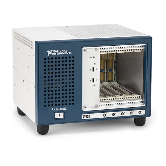
- Page 4 • Handle and rubber feet kit • Fan replacement kit Chassis Components The following figures show key features of the PXIe-1083 chassis front and back panels. Figure 1. Front View of the PXIe-1083 LINK PXIe-1083 1. Thunderbolt 3 MXI-Express Ports 5.
- Page 5 EMC Filler Panels EMC filler panel kits are available from NI. Slot Blockers PXI Slot Blocker kits are available from NI for improved thermal performance when all slots are not used. Handle and Feet Kit An optional side handle and rubber feet kit is available from NI to provide portability.
- Page 6 The PXIe-1083 chassis has a built-in Intel Thunderbolt 3 interface accessible through two Thunderbolt 3 ports on the front of the chassis. This enables control of the PXIe-1083 from a host PC that includes a Thunderbolt 3 port and is running a native (nonvirtualized) operating system that supports Thunderbolt connectivity.
- Page 7 Figure 4. Example of a Daisy-Chain Thunderbolt Link Topology Backwards Compatibility NI recommends connecting the PXIe-1083 to a Thunderbolt 3 port on the host PC using a Thunderbolt 3 cable. Because Thunderbolt 3 is backwards-compatible with previous Thunderbolt generations, it may be possible to use adapters to establish connections with host PCs or devices with previous-generation Thunderbolt ports.
- Page 8 The hybrid peripheral slots provide full PXI Express functionality and 32-bit PXI functionality except for PXI Local Bus. The hybrid peripheral slot connects to only PXI Local Bus 6 left and right. Figure 5. PXIe-1083 PCI Express Backplane Diagram Thunderbolt 3 Controller...
- Page 9 Trigger Bridge #1 System Reference Clock The PXIe-1083 chassis supplies PXI_CLK10, PXIe_CLK100 and PXIe_SYNC100 to every peripheral slot with an independent driver for each signal. An independent buffer (having a source impedance matched to the backplane and a skew of less than 250 ps between slots) drives PXI_CLK10 to each peripheral slot.
- Page 10 PXIe_SYNC100 Installation and Configuration The following section describes how to prepare and operate the PXIe-1083 chassis. Before connecting the chassis to a power source, read this section and the Read Me First: Safety and Electromagnetic Compatibility document included with your kit.
- Page 11 Unsuitable modifications may result in safety hazards. Chassis Cooling Considerations The PXIe-1083 chassis is designed to operate on a bench or in an instrument rack. You must adhere to the cooling clearances as outlined in the following section. Providing Adequate Clearance The module and power supply intake vents are located on the front, left side, and bottom of the chassis.
- Page 12 To aid in thermal health monitoring for either rack or benchtop use you can monitor the chassis intake temperatures in Measurement & Automation Explorer (MAX) to ensure the temperatures do not exceed the ratings in the Operating Environment section of the PXIe-1083 Specifications.
- Page 13 Auto mode. These temperatures may be higher than ambient room temperature depending on surrounding equipment and/or blockages. Ensure ambient intake temperatures do not exceed the ratings in the Operating Environment section of the PXIe-1083 Specifications. The module ambient intake temperatures can be monitored in NI Measurement &...
- Page 14 Setting Fan Speed The PXIe-1083 chassis supports multiple fan operating modes. Refer to the Fan Mode section for more information. Installing Filler Panels To maintain proper module cooling performance, install filler panels (provided with the chassis) in unused or empty slots. Secure with the captive mounting screws provided.
- Page 15 Connecting the Safety Ground Caution The PXIe-1083 chassis are designed with a three-position IEC 60320 C14 inlet for the U.S. that connects the ground line to the chassis ground. For proper grounding, a suitable cordset must be used to connect this inlet to an appropriate earth safety ground.
- Page 16 0.8 m 787580-0R8 Connect the MXI-Express Thunderbolt cable to the host PC Thunderbolt port and PXIe-1083. The cables have no polarity, so you can connect either end to either Thunderbolt port. The cable plugs are reversible, and there is no defined upstream or downstream port on the PXIe-1083.
- Page 17 To power the PXIe-1083 off AC off Observe the PXIe-1083 LED status where applicable. A properly connected and powered up system should report a valid link and power status once the host PC is powered on. Refer to LED Indicators for more information.
- Page 18 3. Peripheral Module Front Panel Mounting Screws (2x) LED Indicators LINK LED The tri-color LINK LED on the PXIe-1083 front panel gives status information about the power supply and link state, as the following table describes. Table 5. LINK LED Colors Color Meaning Power is off.
- Page 19 DIP switch #2 (on the right) controls the chassis Inhibit Mode. Set this switch in the off (down) position to select Default mode. Set this switch in the on (up) position to select Manual mode. PXIe-1083 User Guide | © National Instruments | 19...
- Page 20 In Manual mode, the chassis powers up when you apply AC power and shuts down when you remove AC power. Inhibit Mode Selection You can select the PXIe-1083 chassis Inhibit Mode using a DIP switch on the daughterboard. Refer to the DIP Switches section for the DIP switch location and more information about DIP switch settings.
- Page 21 Refer to the Fan Configuration in MAX section for more information. Alternatively, the fan mode on the PXIe-1083 chassis is selected using a DIP switch on the daughterboard. Refer to the DIP Switches section for more information about the DIP switch.
- Page 22 Trigger Configuration in MAX PXI Platform Services provides an interface to route and reserve triggers so dynamic routing, through drivers such as DAQmx, avoids double-driving and potentially damaging trigger lines. 22 | ni.com | PXIe-1083 User Guide...
- Page 23 Dynamic reservation/routing/deallocation is on the fly within a user program based on NI APIs such as NI-DAQmx. NI recommends dynamic reservations and routing are used whenever possible. If static reservations are required, static reservation of trigger lines can be implemented by the user in MAX through the Triggers tab.
- Page 24 You can configure fan behavior using software settings in MAX The PXIe-1083 supports both Auto and High fan modes for both the 38 W and 58 W cooling profiles. Refer to the Fan Mode section for more information about these modes.
- Page 25 For detailed information regarding initialization files, refer to the PXI Express specification at www.pxisa.org Maintenance This section describes basic maintenance procedures you can perform on the PXIe-1083 chassis. Caution Disconnect the power cable prior to servicing your PXIe-1083 chassis.
- Page 26 Worldwide Support and Services The NI website is your complete resource for technical support. At ni.com/support, you have access to everything from troubleshooting and application development self-help resources to email and phone assistance from NI Application Engineers.
- Page 27 . You can find patents.txt ni.com/patents information about end-user license agreements (EULAs) and third-party legal notices in the readme file for your NI product. Refer to the Export Compliance Information at for the NI global trade compliance policy and how ni.com/legal/export-compliance...
Need help?
Do you have a question about the PXIe-1083 and is the answer not in the manual?
Questions and answers