
Subscribe to Our Youtube Channel
Related Manuals for NI CompactDAQ cDAQ-917 Series


Summary of Contents for NI CompactDAQ cDAQ-917 Series
- Page 1 NI cDAQ -917x User Manual NI CompactDAQ cDAQ-9171/9174/9178 USB Chassis Français Deutsch ni.com/manuals NI cDAQ-917x User Manual May 2013 372838D-01...
- Page 2 Worldwide Technical Support and Product Information ni.com Worldwide Offices Visit ni.com/niglobal to access the branch office Web sites, which provide up-to-date contact information, support phone numbers, email addresses, and current events. National Instruments Corporate Headquarters 11500 North Mopac Expressway Austin, Texas 78759-3504 USA Tel: 512 683 0100...
- Page 3 Warranty NI devices are warranted against defects in materials and workmanship for a period of one year from the invoice date, as evidenced by receipts or other documentation. National Instruments will, at its option, repair or replace equipment that proves to be defective during the warranty period.
- Page 4 For patents covering National Instruments products/technology, refer to the appropriate location: Help»Patents in your software, the file on your media, or the National Instruments Patent Notice at patents.txt ni.com/patents Export Compliance Information Refer to the Export Compliance Information at for the National Instruments global ni.com/legal/export-compliance...
-
Page 5: Table Of Contents
Mounting the cDAQ Chassis on a Panel ..............1-8 NI cDAQ-9171 ....................1-8 NI cDAQ-9174/9178 ..................1-8 Mounting the NI cDAQ-9174/9178 on a DIN Rail ..........1-10 NI cDAQ Chassis Features....................1-11 Chassis Grounding Screw..................1-11 USB Cable Strain Relief................... 1-12 LEDs......................... - Page 6 Serial DIO versus Parallel DIO Modules ..............4-1 Static DIO ......................... 4-1 Digital Input ......................4-2 Digital Input Triggering Signals ...............4-2 Digital Input Timing Signals ................4-2 Digital Input Filters...................4-6 Getting Started with DI Applications in Software..........4-7 vi | ni.com...
- Page 7 Digital Output Data Generation Methods............4-8 Digital Output Triggering Signals ..............4-9 Digital Output Timing Signals ................. 4-10 Getting Started with DO Applications in Software .......... 4-13 Digital Input/Output Configuration for NI 9401 ............4-13 PFI ............................ 4-13 PFI Filters ......................... 4-13 Chapter 5 Counters Counter Timing Engine ....................
- Page 8 Routing Counter n Sample Clock to an Output Terminal ........ 5-36 Counter n Internal Output and Counter n TC Signals ..........5-36 Routing Counter n Internal Output to an Output Terminal ......5-36 Frequency Output Signal ..................5-36 Routing Frequency Output to a Terminal ............5-37 viii | ni.com...
- Page 9 NI cDAQ-917x User Manual Default Counter/Timer Routing..................5-37 Counter Triggering ......................5-37 Other Counter Features..................... 5-38 Cascading Counters ....................5-38 Prescaling........................5-38 Synchronization Modes .................... 5-38 80 MHz Source Mode..................5-39 External or Internal Source Less than 20 MHz ..........5-39...
-
Page 10: Getting Started With The Cdaq Chassis
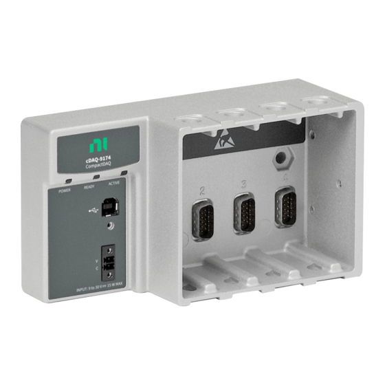
Getting Started with the cDAQ Chassis This chapter provides an NI CompactDAQ chassis overview and lists information about mounting the chassis and installing C Series I/O modules. The one-slot NI cDAQ-9171, four-slot NI cDAQ-9174, and eight-slot NI cDAQ-9178 USB chassis are designed for use with C Series I/O modules. The cDAQ chassis are capable of measuring a broad range of analog and digital I/O signals using a Hi-Speed USB 2.0 interface. -
Page 11: Safety Guidelines
Chassis Grounding Screw 9–30 VDC Power Connector Safety Guidelines Operate the NI cDAQ-917x chassis only as described in this user manual. Refer to the Read Me First: Safety and Electromagnetic Compatibility Caution document for important safety and electromagnetic compatibility information. To... -
Page 12: Safety Guidelines For Hazardous Voltages
Because some C Series I/O modules may have more stringent certification Note standards than the NI cDAQ-917x chassis, the combined system may be limited by individual component restrictions. Refer to the specifications document for your cDAQ chassis for more details. -
Page 13: Unpacking
Remove the device from the package and inspect it for loose components or any other signs of damage. Notify NI if the device appears damaged in any way. Do not install a damaged device in your computer or chassis. -
Page 14: Installing The Cdaq Chassis
Install NI-DAQmx. For more information, download the Read Me First: NI-DAQmx and DAQ Device Installation Guide. The NI-DAQmx software is included on the disk shipped with your kit and is Note available for download at . The documentation for NI-DAQmx is ni.com/support... - Page 15 13. Self-test your chassis in MAX by expanding Devices and Interfaces, right-clicking NI cDAQ-<model number>, and selecting Self-Test. Self-test performs a brief test to determine successful chassis installation. When the self-test finishes, a message indicates 1-6 | ni.com...
-
Page 16: Mounting The Cdaq Chassis
NI 9901 Desktop Kit for NI cDAQ-9174/9178 Chassis The NI 9901 desktop mounting kit includes two metal feet you can install on the sides of the NI cDAQ-9174/9178 chassis for desktop use. With this kit, you can tilt the cDAQ chassis for convenient access to the I/O module connectors. -
Page 17: Mounting The Cdaq Chassis On A Panel
Mounting the cDAQ Chassis on a Panel You do not need a kit to panel mount the NI cDAQ-9171 chassis. You can use a panel mount kit to mount the NI cDAQ-9174/9178 chassis to a panel. For kit accessory ordering information, refer to the pricing section of your cDAQ chassis product page at ni.com... - Page 18 NI cDAQ-917x User Manual with M4, M5, No. 8, or No.10 panhead screws. Refer to the documentation included with the panel mount kit for more detailed dimensions. Figure 1-6. NI cDAQ-9174/9178 Panel Mount Dimensions and Installation 330.2 mm (13.00 in.)
-
Page 19: Mounting The Ni Cdaq-9174/9178 On A Din Rail
Mounting the NI cDAQ-9174/9178 on a DIN Rail Use the NI 9912 DIN rail kit to mount the NI cDAQ-9174 chassis on a DIN rail. Use the NI 9915 DIN rail kit with the NI cDAQ-9178 chassis on a DIN rail. -
Page 20: Ni Cdaq Chassis Features
The cDAQ chassis features a chassis grounding screw, USB cable strain relief, and LEDs. Multislot cDAQ chassis have a power connector and the NI cDAQ-9178 chassis also features two TRIG (PFI) BNC connectors. Refer to Figure 1-1, 1-2, or 1-3 for locations of the cDAQ chassis features. -
Page 21: Usb Cable Strain Relief
The cDAQ chassis features two status LEDs: ACTIVE and READY. The ACTIVE LED indicates cDAQ chassis USB bus communication. The READY LED lights when the cDAQ chassis is ready for use. NI cDAQ-9174/9178 chassis also features a POWER status LED. Table 1-2. LED State/Chassis Status LED Color... -
Page 22: Power Connector
NI cDAQ-917x User Manual Power Connector Refer to the specifications document for your cDAQ chassis for (NI cDAQ-9174/9178) information about the power connector on the NI cDAQ-9174/9178 chassis. TRIG (PFI) BNC Connectors Refer to the section of Chapter 4, Digital Input/Output and... -
Page 23: Using The Cdaq Chassis
For more information about which C Series I/O modules are compatible with the cDAQ chassis, refer to the Developer Zone document, C Series Support in NI-DAQmx. To access this Developer Zone document, go to and enter the Info Code ni.com/info... -
Page 24: Parallel Versus Serial Dio Modules
NI cDAQ-917x User Manual Parallel versus Serial DIO Modules Digital I/O module capabilities are determined by the type of digital signals that the module is capable of measuring or generating. • Serial digital I/O modules are designed for signals that change slowly and are accessed by software-timed reads and writes. - Page 25 PFI signal that, when enabled, samples the input on each rising edge of a filter clock. PFI signals are available through parallel digital input and output modules installed in up to two chassis slots and through the two PFI terminals provided on the NI cDAQ-9178 chassis. Refer to the...
-
Page 26: Analog Input
However, channels from a single module cannot be used in multiple tasks. Multiple timing engines allow the NI cDAQ-9174/9178 to run up to three analog input tasks simultaneously, each using independent timing and triggering configurations. The three AI timing engines are ai, te0, and te1. -
Page 27: Ai Sample Clock Signal
AI Convert Clock Signal Behavior For Analog Input Modules Refer to the Scanned Modules, Simultaneous Sample-and-Hold Modules, Sigma-Delta Modules, Slow Sample Rate Modules sections for information about the AI Convert Clock signal and C Series I/O modules. 2-2 | ni.com... -
Page 28: Scanned Modules
This scheme enables the channels to approximate simultaneous sampling. If the AI Sample Clock rate is too fast to allow for 10 µs of padding, NI-DAQmx selects a conversion rate that spaces the AI Convert Clock pulses evenly throughout the sample. NI-DAQmx uses the same amount of padding for all the modules in the task. -
Page 29: Slow Sample Rate Modules
AI Sample Clock to operate at or slower than their maximum rate. When using such a module in the NI cDAQ-9174/9178 chassis, the maximum Sample Clock rate can run faster than the maximum rate for the module. When operating at a rate faster than these slow rate modules can support, the slow rate module returns the same point repeatedly, until a new conversion completes. -
Page 30: Ai Start Trigger Signal
Using an Analog Source Some C Series I/O modules can generate a trigger based on an analog signal. In NI-DAQmx, this is called the Analog Comparison Event. When you use an analog trigger source for StartTrigger, the acquisition begins on the first rising edge of the Analog Comparison Event signal. -
Page 31: Using A Digital Source
To use Reference Trigger with a digital source, specify a source and a rising or falling edge. Either PFI or one of several internal signals on the cDAQ chassis can provide the source. Refer to the Device Routing in MAX topic in the NI-DAQmx Help or the LabVIEW Help for more information. -
Page 32: Routing The Reference Trigger Signal To An Output Terminal
NI-DAQmx Help or the LabVIEW Help for more information. Using an Analog Source Some C Series I/O modules can generate a trigger based on an analog signal. In NI-DAQmx, this is called the Analog Comparison Event. When you use an analog trigger source, the internal sample clock pauses when the Analog Comparison Event signal is low and resumes when the signal goes high (or vice versa). -
Page 33: Analog Output
Software-Timed Generations With a software-timed generation, software controls the rate at which data is generated. Software sends a separate command to the hardware to initiate each DAC conversion. In NI-DAQmx, software-timed generations are referred to as on-demand timing. Software-timed generations are also referred to as immediate or static operations. -
Page 34: Hardware-Timed Generations
If the program does not write new data to the buffer at a fast enough rate to keep up with the generation, the buffer underflows and causes an error. There is no limitation on the number of waveform channels supported by non-regeneration. 3-2 | ni.com... -
Page 35: Analog Output Triggering Signals
NI cDAQ-917x User Manual Analog Output Triggering Signals Analog output supports two different triggering actions: AO Start Trigger and AO Pause Trigger. An analog or digital trigger can initiate these actions. Up to two C Series parallel digital input modules can be used in any chassis slot to supply a digital trigger. An analog trigger can be supplied by some C Series analog modules. -
Page 36: Routing Ao Sample Clock To An Output Terminal
AO Start Trigger. Using an Analog Source Some C Series I/O modules can generate a trigger based on an analog signal. In NI-DAQmx, this is called the Analog Comparison Event, depending on the trigger properties. When you use an analog trigger source, the waveform generation begins on the first rising or falling edge of the Analog Comparison Event signal, depending on the trigger properties. -
Page 37: Ao Pause Trigger Signal
You also can specify whether the samples are paused when AO Pause Trigger is at a logic high or low level. Refer to the Device Routing in MAX topic in the NI-DAQmx Help or the LabVIEW Help for more information. -
Page 38: Minimizing Glitches On The Output Signal
You can use the cDAQ chassis in the following analog output applications: • Single-point (on-demand) generation • Finite generation • Continuous generation • Waveform generation For more information about programming analog output applications and triggers in software, refer the LabVIEW Help or to the NI-DAQmx Help. 3-6 | ni.com... -
Page 39: Digital Input/Output And Pfi
You can only do hardware timing in one direction at a time on a serial bidirectional module. To determine the capability of digital I/O modules supported by the cDAQ chassis, refer to the Developer Zone document, C Series Support in NI-DAQmx. To access this Developer Zone document, go to and enter the Info Code ni.com/info... -
Page 40: Digital Input
DI waveform acquisition FIFO. If the cDAQ chassis receives a DI Sample Clock signal when the FIFO is full, it reports an overflow error to the host software. 4-2 | ni.com... - Page 41 DI Change Detection Output Several other internal signals can be routed to DI Sample Clock. Refer to the Device Routing in MAX topic in the NI-DAQmx Help or the LabVIEW Help for more information. Using an External Source You can route the following signals as DI Sample Clock: •...
- Page 42 Using an Analog Source Some C Series I/O modules can generate a trigger based on an analog signal. In NI-DAQmx, this is called the Analog Comparison Event. When you use an analog trigger source for DI Start Trigger, the acquisition begins on the first rising edge of the Analog Comparison Event signal.
- Page 43 To use DI Reference Trigger with a digital source, specify a source and a rising or falling edge. Either PFI or one of several internal signals on the cDAQ chassis can provide the source. Refer to the Device Routing in MAX topic in the NI-DAQmx Help or the LabVIEW Help for more information.
-
Page 44: Digital Input Filters
NI-DAQmx Help or the LabVIEW Help for more information. Using an Analog Source Some C Series I/O modules can generate a trigger based on an analog signal. In NI-DAQmx, this is called the Analog Comparison Event. When you use an analog trigger source, the internal sample clock pauses when the Analog Comparison Event signal is low and resumes when the signal goes high (or vice versa). -
Page 45: Getting Started With Di Applications In Software
Continuous acquisition For more information about programming digital input applications and triggers in software, refer to the NI-DAQmx Help or the LabVIEW Help for more information. Change Detection Event The Change Detection Event is the signal generated when a change on the rising or falling edge lines is detected by the change detection task. -
Page 46: Digital Output
Software-Timed Generations With a software-timed generation, software controls the rate at which data is generated. Software sends a separate command to the hardware to initiate each digital generation. In NI-DAQmx, software-timed generations are referred to as on-demand timing. Software-timed generations are also referred to as immediate or static operations. -
Page 47: Digital Output Triggering Signals
NI cDAQ-917x User Manual Buffered Digital Output A buffer is a temporary storage in computer memory for generated samples. In a buffered generation, data is moved from a host buffer to the cDAQ chassis onboard FIFO before it is written to the C Series I/O module(s). -
Page 48: Digital Output Timing Signals
If you are using an internal sample clock, you can specify a delay from the start trigger to the first sample. For more information, refer to the NI-DAQmx Help. 4-10 | ni.com... - Page 49 Using an Analog Source Some C Series I/O modules can generate a trigger based on an analog signal. In NI-DAQmx, this is called the Analog Comparison Event, depending on the trigger properties. When you use an analog trigger source, the waveform generation begins on the first rising or falling edge of the Analog Comparison Event signal, depending on the trigger properties.
- Page 50 You also can specify whether the samples are paused when DO Pause Trigger is at a logic high or low level. Refer to the Device Routing in MAX topic in the NI-DAQmx Help or the LabVIEW Help for more information.
-
Page 51: Getting Started With Do Applications In Software
LabVIEW Help or to the NI-DAQmx Help. Digital Input/Output Configuration for NI 9401 When you change the configuration of lines on a NI 9401 digital I/O module between input and output, NI-DAQmx temporarily reserves all of the lines on the module for communication to send the module a line configuration command. - Page 52 N = 5. Figure 4-7. PFI Filter Example PFI Terminal Filtered input goes high when terminal is sampled high on Filter Clock five consecutive filter clocks. Filtered Input 4-14 | ni.com...
-
Page 53: Counters
Counters The cDAQ chassis has four general-purpose 32-bit counter/timers and one frequency generator. The general-purpose counter/timers can be used for many measurement and pulse generation applications. Figure 5-1 shows the cDAQ chassis Counter 0 and the frequency generator. All four counters on the cDAQ chassis are identical. Figure 5-1. - Page 54 Table 5-1. Counter Timing Measurements Implicit Sample Clocked Measurement Timing Support Timing Support Buffered Edge Count Buffered Pulse Width Buffered Pulse Buffered Semi-Period Buffered Frequency Buffered Period Buffered Position Buffered Two-Signal Edge Separation 5-2 | ni.com...
-
Page 55: Counter Input Applications
NI cDAQ-917x User Manual Counter Input Applications The following sections list the various counter input applications available on the cDAQ chassis: • Counting Edges • Pulse-Width Measurement • Pulse Measurement • Semi-Period Measurement • Frequency Measurement • Period Measurement •... -
Page 56: Buffered (Sample Clock) Edge Counting
Always count up • Always count down • Count up when the Counter 0 B input is high; count down when it is low For information about connecting counter signals, refer to the Default Counter/Timer Routing section. 5-4 | ni.com... -
Page 57: Pulse-Width Measurement
NI cDAQ-917x User Manual Pulse-Width Measurement In pulse-width measurements, the counter measures the width of a pulse on its Gate input signal. You can configure the counter to measure the width of high pulses or low pulses on the Gate signal. -
Page 58: Sample Clocked Buffered Pulse-Width Measurement
Figure 5-7. Sample Clocked Buffered Pulse-Width Measurement Pulse Source Sample Clock Buffer If a pulse does not occur between sample clocks, an overrun error occurs. Note For information about connecting counter signals, refer to the Default Counter/Timer Routing section. 5-6 | ni.com... -
Page 59: Pulse Measurement
The counter begins counting when it is armed. The arm usually occurs between edges on the Gate input but the counting does not start until the desired edge. You can select whether to read the high pulse or low pulse first using the StartingEdge property in NI-DAQmx. © National Instruments | 5-7... -
Page 60: Sample Clocked Buffered Pulse Measurement
Default Counter/Timer Routing section. Semi-Period Measurement In semi-period measurements, the counter measures a semi-period on its Gate input signal after the counter is armed. A semi-period is the time between any two consecutive edges on the Gate input. 5-8 | ni.com... -
Page 61: Single Semi-Period Measurement
The counter begins counting when it is armed. The arm usually occurs between edges on the Gate input. You can select whether to read the first active low or active high semi period using the CI.SemiPeriod.StartingEdge property in NI-DAQmx. Figure 5-11 shows an example of an implicit buffered semi-period measurement. -
Page 62: Pulse Versus Semi-Period Measurements
You can route the signal to measure (fx) to the Gate of a counter. You can route a known timebase (fk) to the Source of the counter. The known timebase can be an onboard timebase, such as 80 MHz Timebase, 20 MHz Timebase, or 100 kHz Timebase, or any other signal with a known rate. 5-10 | ni.com... -
Page 63: High Frequency With Two Counters
NI cDAQ-917x User Manual You can configure the counter to measure one period of the gate signal. The frequency of fx is the inverse of the period. Figure 5-12 illustrates this method. Figure 5-12. Low Frequency with One Counter Interval Measured Gate …... -
Page 64: Large Range Of Frequencies With Two Counters
You can route the signal to measure to the Source input of Counter 0, as shown in Figure 5-14. Assume this signal to measure has frequency fx. NI-DAQmx automatically configures Counter 0 to generate a single pulse that is the width of N periods of the source input signal. -
Page 65: Sample Clocked Buffered Frequency Measurement
NI cDAQ-917x User Manual Sample Clocked Buffered Frequency Measurement Sample clocked buffered point frequency measurements can either be a single frequency measurement or an average between sample clocks. Use CI.Freq.EnableAveraging to set the behavior. For buffered frequency, the default is True. -
Page 66: Choosing A Method For Measuring Frequency
N/fx where N is the divide down. • Sample clocked—For sample clocked frequency measurements, a known timebase is counted for the source frequency (fk). The measurement time is the period of the sample clock (fs). 5-14 | ni.com... -
Page 67: Which Method Is Best
NI cDAQ-917x User Manual Table 5-2. Frequency Measurement Methods Two Counter High Variable Sample Clocked Counter Frequency Large Range Known timebase Known Known timebase timebase ------------------------------- gating period Measurement gating period time --- - --- - --- - Max. ×... - Page 68 50 k and 5 M with a measurement time of 1 ms the error percentage is still close to 0.00125%. One of the disadvantages of a sample clocked frequency measurement is that the frequency to be measured 5-16 | ni.com...
-
Page 69: Period Measurement
NI cDAQ-917x User Manual must be at least twice the sample clock rate to ensure that a full period of the frequency to be measured occurs between sample clocks. • Low frequency measurements with one counter is a good method for many applications. -
Page 70: Position Measurement
When channel A leads channel B, the increment occurs on the rising edge of channel A. When channel B leads channel A, the decrement occurs on the falling edge of channel A. Figure 5-17. X1 Encoding Ch A Ch B Counter Value 5-18 | ni.com... -
Page 71: Channel Z Behavior
NI cDAQ-917x User Manual • X2 Encoding—The same behavior holds for X2 encoding except the counter increments or decrements on each edge of channel A, depending on which channel leads the other. Each cycle results in two increments or decrements, as shown in Figure 5-18. -
Page 72: Measurements Using Two Pulse Encoders
You can route the counter sample clock to the Gate input of the counter. You can configure the counter to sample on the rising or falling edge of the sample clock. 5-20 | ni.com... -
Page 73: Two-Signal Edge-Separation Measurement
NI cDAQ-917x User Manual Figure 5-22 shows an example of a buffered X1 position measurement. Figure 5-22. Buffered Position Measurement Counter Armed Sample Clock (Sample on Rising Edge) Ch A Ch B Count Buffer Two-Signal Edge-Separation Measurement Two-signal edge-separation measurement is similar to pulse-width measurement, except that there are two measurement signals—Aux and Gate. -
Page 74: Implicit Buffered Two-Signal Edge-Separation Measurement
Aux signal. The counter then stores the count in the FIFO on a sample clock edge. On the next active edge of the Gate signal, the counter begins another measurement. The STC3 transfers the sampled values to host memory using a high-speed data stream. 5-22 | ni.com... -
Page 75: Counter Output Applications
NI cDAQ-917x User Manual Figure 5-25 shows an example of a sample clocked buffered two-signal separation measurement. Figure 5-25. Sample Clocked Buffered Two-Signal Separation Measurement Sample Clock GATE SOURCE Counter Value Buffer If an active edge on the Gate and an active edge on the Aux does not occur Note between sample clocks, an overrun error occurs. -
Page 76: Single Pulse Generation With Start Trigger
Refer to the following sections for more information about the cDAQ chassis pulse train generation options: • Finite Pulse Train Generation • Retriggerable Pulse or Pulse Train Generation • Continuous Pulse Train Generation • Buffered Pulse Train Generation • Finite Implicit Buffered Pulse Train Generation 5-24 | ni.com... -
Page 77: Finite Pulse Train Generation
NI cDAQ-917x User Manual • Continuous Buffered Implicit Pulse Train Generation • Finite Buffered Sample Clocked Pulse Train Generation • Continuous Buffered Sample Clocked Pulse Train Generation Finite Pulse Train Generation This function generates a train of pulses with programmable frequency and duty cycle for a predetermined number of pulses. -
Page 78: Continuous Pulse Train Generation
You specify the high and low pulse widths of the output signal. The pulse widths are also measured in terms of a number of active edges of the Source input. You also can specify the active edge of the Source input (rising or falling). 5-26 | ni.com... -
Page 79: Buffered Pulse Train Generation
NI cDAQ-917x User Manual The counter can begin the pulse train generation as soon as the counter is armed, or in response to a hardware Start Trigger. You can route the Start Trigger to the Gate input of the counter. -
Page 80: Continuous Buffered Implicit Pulse Train Generation
Table 5-7 and Figure 5-33 detail a finite sample clocked generation of three samples where the pulse specifications from the create channel are two ticks idle, two ticks active, and three ticks initial delay. Table 5-7. Finite Buffered Sample Clocked Pulse Train Generation Sample Idle Ticks Active Ticks 5-28 | ni.com... -
Page 81: Continuous Buffered Sample Clocked Pulse Train Generation
NI cDAQ-917x User Manual Table 5-7. Finite Buffered Sample Clocked Pulse Train Generation (Continued) Sample Idle Ticks Active Ticks Figure 5-33. Finite Buffered Sample Clocked Pulse Train Generation Counter Armed Sample Clock Counter 2 1 0 1 0 1 0 1... -
Page 82: Using The Frequency Generator
The FREQ OUT signal also can be routed to many internal timing signals. In software, program the frequency generator as you would program one of the counters for pulse train generation. For information about connecting counter signals, refer to the Default Counter/Timer Routing section. 5-30 | ni.com... -
Page 83: Frequency Division
NI cDAQ-917x User Manual Frequency Division The counters can generate a signal with a frequency that is a fraction of an input signal. This function is equivalent to continuous pulse train generation. Refer to the Continuous Pulse Train Generation section for detailed information. -
Page 84: Counter Timing Signals
Table 5-8. Counter Applications and Counter n Source Application Purpose of Source Terminal Pulse Generation Counter Timebase One Counter Time Measurements Counter Timebase Two Counter Time Measurements Input Terminal Non-Buffered Edge Counting Input Terminal Buffered Edge Counting Input Terminal Two-Edge Separation Counter Timebase 5-32 | ni.com... -
Page 85: Routing A Signal To Counter N Source
In addition, TC or Gate from a counter can be routed to a different counter source. Some of these options may not be available in some driver software. Refer to the Device Routing in MAX topic in the NI-DAQmx Help or the LabVIEW Help for more information about available routing options. -
Page 86: Routing Counter N Gate To An Output Terminal
Counters Some of these options may not be available in some driver software. Refer to the Device Routing in MAX topic in the NI-DAQmx Help or the LabVIEW Help for more information about available routing options. Routing Counter n Gate to an Output Terminal You can route Counter n Gate out to any PFI terminal. -
Page 87: Counter N Up_Down Signal
A counter’s Internal Output can be routed to a different counter’s HW Arm. Some of these options may not be available in some driver software. Refer to the Device Routing in MAX topic in the NI-DAQmx Help or the LabVIEW Help for more information about available routing options. -
Page 88: Using An Internal Source
DI Change Detection output Several other internal signals can be routed to Counter n Sample Clock through internal routes. Refer to Device Routing in MAX in the NI-DAQmx Help or the LabVIEW Help for more information. Using an External Source You can route any of the following signals as Counter n Sample Clock: •... -
Page 89: Routing Frequency Output To A Terminal
You can use these defaults or select other sources and destinations for the counter/timer signals in NI-DAQmx. Refer to Connecting Counter Signals in the NI-DAQmx Help or the LabVIEW Help for more information about how to connect your signals for common counter measurements and generations. -
Page 90: Other Counter Features
Depending on how you configure your chassis, the cDAQ chassis uses one of two synchronization methods: • 80 MHz Source Mode • External or Internal Source Less than 20 MHz 5-38 | ni.com... -
Page 91: 80 Mhz Source Mode
NI cDAQ-917x User Manual 80 MHz Source Mode In 80 MHz source mode, the chassis synchronizes signals on the rising edge of the source, and counts on the third rising edge of the source. Edges are pipelined so no counts are lost, as shown in Figure 5-38. -
Page 92: Digital Routing And Clock Generation
Your C Series I/O modules – User input through the PFI terminals using parallel digital C Series I/O modules or the NI cDAQ-9178 chassis PFI terminals • Routes and generates the main clock signals for the cDAQ chassis. To determine the signal routing options for C Series I/O module(s) installed in the cDAQ chassis, refer to the Device Routes tab in MAX. -
Page 93: 20 Mhz Timebase
You can use the 100 kHz Timebase to generate many of the AI and AO timing signals. It can also function as the Source input to the 32-bit general-purpose counter/timers. The 100 kHz Timebase is generated by dividing down the 20 MHz Timebase by 200, as shown in Figure 6-1. 6-2 | ni.com... -
Page 94: Appendix A Where To Go From Here
NI-DAQmx 9.7 or later. NI cDAQ Chassis Documentation The NI cDAQ-91xx Quick Start packaged with your cDAQ chassis, describes how to install your NI-DAQmx for Windows software, how to install the cDAQ chassis and C Series I/O module, and how to confirm that your device is operating properly. - Page 95 Appendix A Where to Go from Here NI-DAQmx The NI-DAQ Readme lists which devices, ADEs, and NI application software are supported by this version of NI-DAQ. Select Start»All Programs»National Instruments»NI-DAQ» NI-DAQ Readme. The NI-DAQmx Help contains API overviews, general information about measurement concepts, key NI-DAQmx concepts, and common applications that are applicable to all programming environments.
- Page 96 Choose a programming language (Visual C# or Visual Basic .NET), and then select Measurement Studio to see a list of project templates. Select NI DAQ Windows Application. You add DAQ tasks as part of this step. Choose a project type. You add DAQ tasks as a part of this step.
- Page 97 Visual C# and Visual Basic .NET without Measurement Studio. Refer to the NI-DAQmx Readme for specific versions supported. Training Courses If you need more help getting started developing an application with NI products, NI offers training courses. To enroll in a course or obtain a detailed course outline, refer to ni.com/...
- Page 98 Engineers make sure every question submitted online receives an answer. – Standard Service Program Membership—This program entitles members to direct access to NI Applications Engineers via phone and email for one-to-one technical support, as well as exclusive access to self-paced online training modules at ni.com/ .
- Page 99 Appendix B Technical Support and Professional Services You also can visit the Worldwide Offices section of to access the branch ni.com/niglobal office Web sites, which provide up-to-date contact information, support phone numbers, email addresses, and current events. B-2 | ni.com...
- Page 100 C Series I/O module, 1-14 acquisitions, digital waveform, 4-2 C Series module specifications, A-1 analog input cables, 1-13 getting started with applications in calibration certificate (NI resources), B-1 software, 2-7 cascading counters, 5-38 timing signals, 2-1 cDAQ chassis triggering, 2-1...
- Page 101 (NI resources), B-1 data edge counting, 5-3 AO generation methods, 3-1 buffered, 5-4 DO generation methods, 4-8 on-demand, 5-3 Declaration of Conformity (NI resources), sample clock, 5-4 single point, 5-3 diagnostic tools (NI resources), B-1 edge-separation measurement digital I/O buffered two-signal, 5-22...
- Page 102 5-5 division, 5-31 semi-period measurement, 5-9 generation, 5-29 installation, 1-5 generator, 5-30 instrument drivers (NI resources), B-1 measurement, 5-10 Frequency Output signal, 5-36 KnowledgeBase, B-1 generations analog output data, 3-1 LabVIEW documentation, A-2 buffered hardware-timed...
- Page 103 National Instruments support and safety guidelines, 1-2 services, B-1 for hazardous voltages, 1-3 .NET languages documentation, A-4 sample clock measurement, 5-20 NI support and services, B-1 sample clock, edge counting, 5-4 NI-DAQmx semi-period measurement, 5-8 device documentation browser, A-1 implicit buffered, 5-9...
- Page 104 NI cDAQ-917x User Manual technical support, A-4, B-1 timebase 100 kHz, 6-2 20 MHz, 6-2 80 MHz, 6-1 training, A-4 training and certification (NI resources), B-1 TRIG (PFI) BNC connectors, 1-13 trigger arm start, 5-37 pause, 5-37 start, 5-37 troubleshooting (NI resources), B-1...
Need help?
Do you have a question about the CompactDAQ cDAQ-917 Series and is the answer not in the manual?
Questions and answers