Table of Contents
Advertisement
Quick Links
Advertisement
Table of Contents

Subscribe to Our Youtube Channel
Related Manuals for NI NI-9154


Summary of Contents for NI NI-9154
- Page 1 NI-9154 Getting Started 2022-07-06...
-
Page 2: Table Of Contents
What You Need to Install the NI-9154........ -
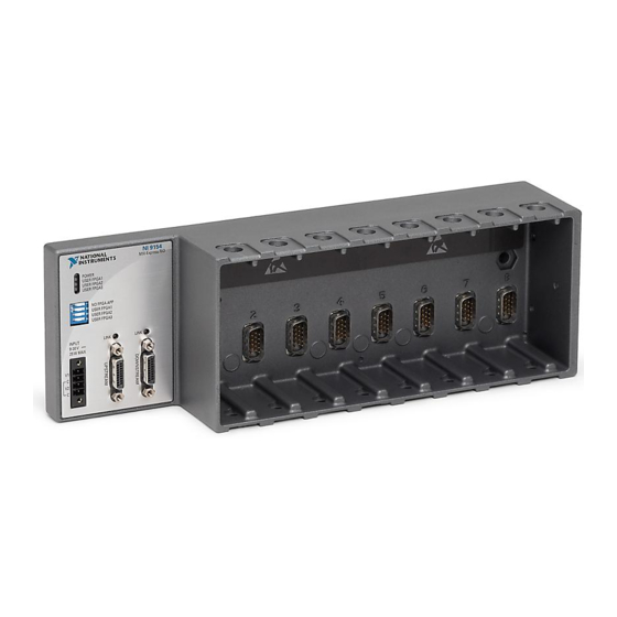
Page 3: Overview
NI-9154 Getting Started Overview This document describes how to begin using the NI-9154. Safety Guidelines Caution Observe all instructions and cautions in the user documentation. Using the model in a manner not specified can damage the model and compromise the built-in safety protection. Return damaged models to NI for repair. - Page 4 Safety Guidelines for Hazardous Locations The NI-9154 is suitable for use in Class I, Division 2, Groups A, B, C, D, T4 hazardous locations; Class I, Zone 2, AEx nA IIC T4 Gc and Ex nA IIC T4 Gc hazardous locations;...
-
Page 5: Electromagnetic Compatibility Guidelines
NI-9154 Getting Started Caution Transient protection shall be provided that is set at a level not exceeding 140% of the peak rated voltage value of 85 V at the supply terminals to the equipment. Caution The system shall only be used in an area of not more than Pollution Degree 2, as defined in IEC/EN 60664-1. -
Page 6: Preparing The Environment
EMC performance is attained. Preparing the Environment Ensure that the environment in which you are using the NI-9154 meets the following specifications. Operating temperature (IEC 60068-2-1, IEC 60068-2-2) 0 °C to 55 °C... -
Page 7: Installing C Series Modules
NI cRIO-9081/9082 integrated system ■ Note The NI-9154 requires a host system with a PCI Express clock that complies with the PCI Express Specification. The NI-9154 may not be compatible with systems using noncompliant clocks, particularly clocks with peak frequencies higher than 100 MHz. For more... -
Page 8: Removing C Series Modules
NI-9154 Getting Started Complete the following steps to install a C Series I/O module in the chassis. 1. Make sure that no I/O-side power is connected to the I/O module. If the system is in a nonhazardous location, the chassis power can be on when you install I/O modules. -
Page 9: Connecting The Ni 9154 To Ground
Complete the following steps to ground the NI 9154. 1. Attach the ring lug to the wire. 2. Remove the grounding screw from the grounding terminal on the NI 9154. 3. Attach the ring lug to the grounding terminal. 4. Tighten the grounding screw to 0.5 N · m (4.4 lb · in.) of torque. - Page 10 Connecting One or More NI-9154 Chassis to the MXI-Express Host System or a Target Complete the following steps to connect one or more NI-9154 chassis to a MXI- Express host system or a target. 1. Make sure the MXI-Express host system is set up and configured as described in the MXI-Express (x1) Series User Manual.
-
Page 11: Wiring Power To The Chassis
The NI-9154 requires an external power supply that meets the specifications. The NI-9154 filters and regulates the supplied power and provides power for all of the I/O modules. You must connect a power supply to at least one pair of V and C terminals. -
Page 12: Checking Mxi-Express Link Leds For Status
Table 2. Chassis Powerup Options If you want the NI-9154 to autoload and run a VI at powerup, you must also configure the VI to autoload before you compile it. For more information about autoloading VIs, refer to the LabVIEW FPGA Module Help. -
Page 13: Where To Go Next
NI product. Product registration facilitates technical support and ensures that you receive important information updates from NI corporate headquarters is located at 11500 N Mopac Expwy, Austin, TX, 78759-3504, USA. © National Instruments © 2022 National Instruments Corporation.
Need help?
Do you have a question about the NI-9154 and is the answer not in the manual?
Questions and answers