Table of Contents
Advertisement
Advertisement
Table of Contents

Subscribe to Our Youtube Channel
Related Manuals for NI PXI-1033


Summary of Contents for NI PXI-1033
- Page 1 NI PXI-1033 User Manual NI PXI-1033 User Manual May 2012 371991C-01...
- Page 2 For further support information, refer to the Technical Support and Professional Services appendix. To comment on National Instruments documentation, refer to the National Instruments Web site at ni.com/info and enter the Info Code feedback. © 2006–2012 National Instruments. All rights reserved.
- Page 3 Warranty The PXI-1033 is warranted against defects in materials and workmanship for a period of one year from the date of shipment, as evidenced by receipts or other documentation. National Instruments will, at its option, repair or replace equipment that proves to be defective during the warranty period.
- Page 4 THE USER OR APPLICATION DESIGNER MUST TAKE REASONABLY PRUDENT STEPS TO PROTECT AGAINST SYSTEM FAILURES, INCLUDING BUT NOT LIMITED TO BACK-UP OR SHUT DOWN MECHANISMS. BECAUSE EACH END-USER SYSTEM IS CUSTOMIZED AND DIFFERS FROM NATIONAL INSTRUMENTS' TESTING PLATFORMS AND BECAUSE A USER OR APPLICATION DESIGNER MAY USE NATIONAL INSTRUMENTS PRODUCTS IN COMBINATION WITH OTHER PRODUCTS IN A MANNER NOT EVALUATED OR CONTEMPLATED BY NATIONAL INSTRUMENTS, THE USER OR APPLICATION DESIGNER IS ULTIMATELY RESPONSIBLE FOR VERIFYING AND VALIDATING THE SUITABILITY OF NATIONAL INSTRUMENTS PRODUCTS WHENEVER...
- Page 5 The Declaration of Conformity (DoC) contains important EMC compliance information and instructions for the user or installer. To obtain the DoC for this product, visit , search by model number or product line, ni.com/certification and click the appropriate link in the Certification column.
-
Page 6: Table Of Contents
Connecting Safety Ground.....................2-4 Connecting to Power Source..................2-4 Getting Started With The System ..................2-4 Unpacking The MXI-Express Host Card...............2-5 Hardware Installation.....................2-5 Installing an NI ExpressCard Module .............2-5 Installing an NI PCI Express Host Card............2-7 © National Instruments NI PXI-1033 User Manual... - Page 7 Preparation........................3-1 Cleaning......................... 3-1 Interior Cleaning ..................... 3-2 Exterior Cleaning .................... 3-2 Cleaning and Replacing the Fan Filter ................3-2 Appendix A Specifications Appendix B Pinouts Appendix C Technical Support and Professional Services Glossary Index NI PXI-1033 User Manual ni.com...
-
Page 8: About This Manual
About This Manual The NI PXI-1033 User Manual contains information about installing, configuring, using, and maintaining the NI PXI-1033 chassis. Conventions The following conventions are used in this manual: » The » symbol leads you through nested menu items and dialog box options to a final action. -
Page 9: Related Documentation
• PXI Software Specification • IEEE 1101.1-1991, IEEE Standard for Mechanical Core Specifications for Microcomputers Using IEC 603-2 Connectors • IEEE 1101.10, IEEE Standard for Additional Mechanical Specifications for Microcomputers Using IEEE 1101.1 Equipment Practice NI PXI-1033 User Manual ni.com... -
Page 10: Getting Started
Getting Started This chapter describes the key features of the NI PXI-1033 chassis, and lists the kit contents and optional equipment you can order from National Instruments. Unpacking Carefully inspect the shipping container and the chassis for damage. Check for visible damage to the metal work. Check to make sure all handles, hardware, and switches are undamaged. -
Page 11: Key Features
If you are missing any of the items listed in Table 1-1, or if you have the incorrect AC power cable, contact National Instruments. Key Features The NI PXI-1033 combines a 5-slot PXI backplane with a structural design that has been optimized for maximum usability in a wide range of applications. -
Page 12: Chassis Description
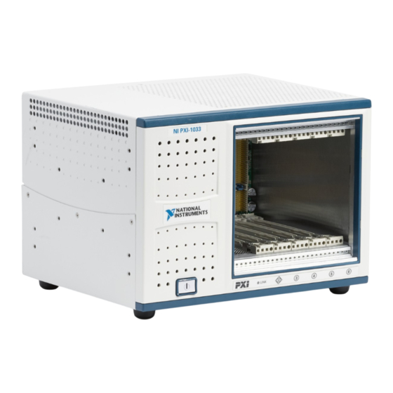
Getting Started Chassis Description Figure 1-1 and Figure 1-2 show the key features of the NI PXI-1033 chassis front and rear panels. Figure 1-1 shows the front view of the NI PXI-1033. Figure 1-2 shows the rear view of the NI PXI-1033. - Page 13 5 Chassis Ground Screw 2 AC Input 6 Auto/High Fan Speed Selector Switch 3 Power Supply Fan Exhaust 7 Rubber Foot 4 NI MXI-Express Chassis Controller Connector Figure 1-2. Rear View of the NI PXI-1033 Chassis NI PXI-1033 User Manual ni.com...
-
Page 14: Optional Equipment
EMC Filler Panels Optional EMC filler panel kits are available from National Instruments. Rack Mount Kit A rack mount kit option is available for mounting the NI PXI-1033 chassis into a 19 in. instrument cabinet. Handle/Feet Kit An optional side handle and rubber feet kit is available from National Instruments to provide a handle for portability. -
Page 15: Ni Pxi-1033 Backplane Overview
64-bit specification. Therefore, all modules that meet the requirements of the CompactPCI 64-bit specification will function in the NI PXI-1033. Refer to Appendix B, Pinouts, for pinout information. The NI PXI-1033 backplane is 32-bit PCI. 64-bit CompactPCI cards will operate in Note 32-bit mode in this chassis. -
Page 16: Peripheral Slots
Initialization software uses the configuration information specific to adjacent peripheral modules to evaluate local bus compatibility. Star Triggers Local Local Local Local Embedded PCI Arbitration and Clock Signals Controller Figure 1-4. PXI Star Trigger and Local Bus Routing © National Instruments NI PXI-1033 User Manual... -
Page 17: Trigger Bus
System Reference Clock The NI PXI-1033 supplies the PXI 10 MHz system clock signal (PXI_CLK10) independently to each peripheral slot. An independent buffer (having a source impedance matched to the backplane and a skew of less than 250 ps between slots) drives the clock signal to each peripheral slot. -
Page 18: Installation And Configuration
Installation and Configuration This chapter describes how to install, configure, and use the NI PXI-1033 chassis. Before connecting the chassis to a power source, read this chapter and the Read Me First: Safety and Electromagnetic Compatibility document included with your chassis. -
Page 19: Chassis Cooling Considerations
Figure 2-1. Air cooling the power supply enters the front of the chassis, which is shown in Figure 1-1, Front View of the NI PXI-1033 Chassis, then exits through the rear of the chassis, which is shown in... -
Page 20: Setting Fan Speed
Installation and Configuration 1 Air Outlets 2 Air Intake Figure 2-1. NI PXI-1033 Module Cooling Airflow Side View Install the chassis so that you can easily access the bottom panel. This simplifies replacing the air filters, if necessary. Setting Fan Speed The AUTO/HIGH fan-speed selector switch is on the rear panel of the NI PXI-1033. -
Page 21: Rack Mounting
Connecting Safety Ground The NI PXI-1033 chassis is designed with a three-position inlet that connects the Caution cord set ground line to the chassis ground. To minimize shock hazard, make sure the electrical power outlet you use to power the chassis has an appropriate earth safety ground. -
Page 22: Unpacking The Mxi-Express Host Card
The software for your MXI-Express kit is included with the current NI driver CD, Note and is installed with the PXI platform software included as part of NI-VISA and other NI driver software products. Installing an NI ExpressCard Module... - Page 23 Chapter 2 Installation and Configuration Connect the cable to the NI ExpressCard module and the NI PXI-1033 chassis. Plug the NI ExpressCard module into an available ExpressCard slot. If your computer is already running (or hibernating) when you install NI ExpressCard module, you must reboot to detect the PXI system.
-
Page 24: Installing An Ni Pci Express Host Card
Select any available PCI Express expansion slot (x1 or wider). Note The BIOS or motherboard may not support the NI PCI Express host card in a slot intended for a graphics card. Locate the metal bracket that covers the cut-out in the back panel of the computer for the slot you have selected. - Page 25 Chapter 2 Installation and Configuration 1 NI PCI Express Host Card 3 PCI Express Slot 2 PCI Express x1 Card-Edge Connector Figure 2-3. Installing the NI PCI Express Host Card NI PXI-1033 User Manual ni.com...
-
Page 26: Cabling
Cabling Connect the appropriate MXI-Express cable to the NI PCI Express card and NI PXI-1033 chassis. The cables have no polarity, so either end may be connected to either connector. Do not remove the cable after the system is powered on. Doing so can hang Caution or cause errors in applications communicating with devices behind MXI-Express. -
Page 27: Powering Up The Mxi-Express System
Refer to the MXI-3 or MXI-4 documentation for further details. The NI PXI-1033 chassis will assert a wake signal on power up. The host PC also will power on if it supports this functionality. -
Page 28: Checking Leds For Status
Chapter 2 Installation and Configuration Checking LEDs for Status After powering on the NI PXI-1033 chassis you should check the LEDs for status to ensure that all connected systems have linked. The following table defines the LED states. Table 2-1. LED Status for the NI PXI-1033 Chassis... -
Page 29: Mxi-Express Cable Options
Note You must install the driver software provided on the NI Driver CD supplied with your kit before you can use the modules in the chassis. NI PXI-1033 User Manual 2-12 ni.com... -
Page 30: Pxi System Configuration With Max
PXI system. After installing the software on the NI Driver CD-ROM, the MAX icon will be present on the desktop. The configuration steps for single or multiple chassis systems are the same. © National Instruments... -
Page 31: Basic Pxi System Configuration
Figure 2-6. Chassis Configuration in MAX Basic PXI System Configuration The Platform Services 2.1 (or higher) software provided on the NI Driver CD-ROM will automatically detect your NI PXI-1033 chassis. To manually configure your chassis follow the steps outlined below. Refer to Figure 2-6 while completing the following steps: Launch MAX. -
Page 32: Trigger Configuration In Max
Identify As submenu. Further expanding the PXI System branch will show all of the devices in the system that can be recognized by NI-VISA. After your controller and all of your chassis have been identified, the required file will be complete. -
Page 33: Using System Configuration And Initialization Files
.ini The capability documentation for the NI PXI-1033 chassis is contained in file on the software media that comes with the chassis. chassis.ini The information in this file is combined with information about the system controller to create a single system initialization file called pxisys.ini... -
Page 34: Maintenance
Maintenance This chapter describes basic maintenance procedures you can perform on the NI PXI-1033 chassis. Caution Disconnect the power cables prior to servicing the chassis. Service Interval Clean the chassis fan filter at a maximum interval of six months. Depending on the amount of use and ambient dust levels in the operating environment, the filter may require more frequent cleaning. -
Page 35: Interior Cleaning
To remove the filter cover, loosen the retainer screw. The filter cover is shown in Figure 1-3, Bottom View of the NI PXI-1033 Chassis. Clean the fan filter by washing it in a mild soap solution and then vacuuming or blowing air through it. -
Page 36: Appendix A Specifications
Specifications Caution If the NI PXI-1033 chassis is used in a manner inconsistent with the instructions or specifications listed by National Instruments, the protective features of the chassis may be impaired. Specifications are subject to change without notice. Note This appendix contains specifications for the NI PXI-1033 chassis. - Page 37 Slot airflow direction ......P1 to P2, bottom of module to top of module Module cooling System ..........Forced air circulation (positive pressurization) through a 101.1 CFM fan with High/Auto speed selector Intake ..........Bottom of chassis Exhaust ..........Along rear, right side, and top of chassis NI PXI-1033 User Manual ni.com...
- Page 38 Storage Environment Ambient temperature range....–40 to 85 °C (Tested in accordance with IEC-60068-2-1 and IEC-60068-2-2. Meets MIL-PRF-28800F Class 3 limits.) Relative humidity range ......10 to 95%, noncondensing (Tested in accordance with IEC-60068-2-56.) © National Instruments NI PXI-1033 User Manual...
- Page 39 NI PXI-1033 Auto fan (at 25 °C ambient) ....37.4 dBA High fan ...........51.5 dBA Sound Power Tested in accordance with ISO 7779. NI PXI-1033 Auto fan (at 25 °C ambient) ....43.8 dBA High fan ...........60.9 dBA NI PXI-1033 User Manual ni.com...
- Page 40 For EMC declarations and certifications, and additional information, refer to the Online Product Certification section. CE Compliance This product meets the essential requirements of applicable European Directives as follows: • 2006/95/EC; Low-Voltage Directive (safety) • 2004/108/EC; Electromagnetic Compatibility Directive (EMC) © National Instruments NI PXI-1033 User Manual...
- Page 41 Certification column. Environmental Management NI is committed to designing and manufacturing products in an environmentally responsible manner. NI recognizes that eliminating certain hazardous substances from our products is beneficial to the environment and to NI customers.
- Page 42 Weight..........5 kg (11.0 lbs) Chassis materials........Sheet Aluminum, Extruded Aluminum, Cold Rolled Steel, Nylon Finish............Clear Chromate Conversion Coat on Aluminum Electrodeposited Nickel Plate Plate on Cold Rolled Steel Polyester Urethane Powder Paint © National Instruments NI PXI-1033 User Manual...
- Page 43 Appendix A Specifications Figure A-1 and Figure A-2 show the NI PXI-1033 dimensions. The holes shown are for the installation of the optional rack-mount kits as shown in Figure A-3. Notice that the front and rear rack mounting holes (size M4) are symmetrical.
- Page 44 Appendix A Specifications M4 × 0.7 0.96 in. 0.25 in. (6.35 mm) Max, 4× (24.38 mm) 6.49 in. (164.85 mm) 0.69 in. 8.74 in. (222 mm) (17.5 mm) Figure A-2. NI PXI-1033 Dimensions (Bottom) © National Instruments NI PXI-1033 User Manual...
- Page 45 Appendix A Specifications Figure A-3 shows the NI PXI-1033 rack mount kit components. 1 NI PXI-1033 Chassis 2 Rack Mount Kit Figure A-3. NI PXI-1033 Rack Mount Kit Components NI PXI-1033 User Manual A-10 ni.com...
-
Page 46: Appendix B Pinouts
Pinouts This appendix describes the P1 and P2 connector pinouts for the NI PXI-1033/NI PXI-1033 backplane. Table B-1 shows the P1 (J1) Connector Pinout for the star trigger slot. Table B-2 shows the P2 (J2) Connector Pinout for the star trigger slot. - Page 47 AD[21] 3.3V AD[20] AD[19] C/BE[3]# IDSEL AD[23] AD[22] AD[26] V(I/O) AD[25] AD[24] AD[30] AD[29] AD[28] AD[27] REQ# 3.3V AD[31] BRSVP1A5 BRSVP1B5 RST# GNT# IPMB_PWR HEALTHY# V(I/O) INTP INTS INTA# INTB# INTC# INTD# –12V TRST# +12V NI PXI-1033 User Manual ni.com...
- Page 48 PXI_STAR5 PXI_TRIG3 PXI_TRIG4 PXI_TRIG5 PXI_TRIG6 PXI_TRIG2 PXI_CLK10_IN PXI_CLK10 PXI_TRIG1 PXI_TRIG0 PXI_TRIG7 PXI_BRSVA15 PXI_STAR6 PXI_LBR6 V(I/O) V(I/O) V(I/O) V(I/O) V(I/O) V(I/O) PXI_BRSVB4 PXI_LBR7 PXI_LBR8 PXI_LBR9 PXI_LBR10 PXI_LBR11 PXI_LBR12 PXI_STAR7 PXI_STAR8 PXI_STAR9 PXI_STAR10 PXI_STAR11 PXI_STAR12 © National Instruments NI PXI-1033 User Manual...
- Page 49 AD[21] 3.3V AD[20] AD[19] C/BE[3]# IDSEL AD[23] AD[22] AD[26] V(I/O) AD[25] AD[24] AD[30] AD[29] AD[28] AD[27] REQ# 3.3V AD[31] BRSVP1A5 BRSVP1B5 RST# GNT# IPMB_PWR HEALTHY# V(I/O) INTP INTS INTA# INTB# INTC# INTD# –12V TRST# +12V NI PXI-1033 User Manual ni.com...
- Page 50 PXI_LBL5 PXI_TRIG3 PXI_TRIG4 PXI_TRIG5 PXI_TRIG6 PXI_TRIG2 PXI_STAR PXI_CLK10 PXI_TRIG1 PXI_TRIG0 PXI_TRIG7 PXI_BRSVA15 PXI_LBL6 PXI_LBR6 V(I/O) V(I/O) V(I/O) V(I/O) V(I/O) V(I/O) 64EN# PXI_LBR7 PXI_LBR8 PXI_LBR9 PXI_LBR10 PXI_LBR11 PXI_LBR12 PXI_LBL7 PXI_LBL8 PXI_LBL9 PXI_LBL10 PXI_LBL11 PXI_LBL12 © National Instruments NI PXI-1033 User Manual...
- Page 51 KnowledgeBase, product manuals, step-by-step troubleshooting wizards, thousands of example programs, tutorials, application notes, instrument drivers, and so on. Registered users also receive access to the NI Discussion Forums . NI Applications Engineers make sure every ni.com/forums question submitted online receives an answer.
- Page 52 You also can visit the Worldwide Offices section of ni.com/niglobal to access the branch office Web sites, which provide up-to-date contact information, support phone numbers, email addresses, and current events. NI PXI-1033 User Manual ni.com...
- Page 53 Symbols ° Degrees ≥ Equal or greater than ≤ Equal or less than Percent Ω Ohms Amperes Alternating current ANSI American National Standards Institute AUTO Automatic fan speed control American Wire Gauge © National Instruments NI PXI-1033 User Manual...
- Page 54 A method of propagating signals along a bus, in which the devices are prioritized on the basis of their position on the bus Direct current Declaration of Conformity efficiency Ratio of output power to input power, expressed as a percentage Electronic Industries Association NI PXI-1033 User Manual ni.com...
- Page 55 A measure of random vibration; the root mean square of acceleration levels in a random vibration test profile Hours Hertz—Cycles per second International Electrotechnical Commission—An organization that sets international electrical and electronics standards IEEE Institute of Electrical and Electronics Engineers Mainframe peak current © National Instruments NI PXI-1033 User Manual...
- Page 56 Meters NI Measurement & Automation Explorer, the utility that allows you to configure and test your PXI system Megahertz—One million Hertz; one Hertz equals one cycle per second Millisecond—One thousandth of a second (10...
- Page 57 Instruments data acquisition (DAQ) devices NI-VISA National Instruments implementation of the VISA (Virtual Instrument System Architecture) I/O standard. NI-VISA provides support for the VISA API, and also provides VISAIC, a utility for instrument configuration and I/O function execution. Nanosecond—One billionth of a second (10 –9...
- Page 58 The system reference clock can be used for synchronization of multiple modules in a measurement or control system. The PXI backplane specification defines implementation guidelines for PXI_CLK10. Transistor-transistor logic Underwriter’s Laboratories Volts Volts alternating current, or V Peak-to-peak voltage Watts NI PXI-1033 User Manual ni.com...
- Page 59 Index Numerics conventions used in the manual, viii cooling 10 MHz system reference clock, A-7 air cooling of NI PXI-1033, 2-2 air intake (figure), 2-3 filler panel installation, 2-3 setting fan speed, 2-3 AC power cables (table), 1-2 Declaration of Conformity (NI resources), C-2...
- Page 60 NI PXI-1033, 3-1 hardware, 2-5 cleaning of an NI ExpressCard module, 2-5 exterior cleaning, 3-2 of an NI PCI Express host card, 2-7 fan filter, 3-2 powering down the MXI-Express system, 2-10 interior cleaning, 3-2 powering up the MXI-Express...
- Page 61 Index fan speed, setting, 2-3 programming examples (NI resources), C-1 front view (figure), 1-3 PXI_CLK10, 1-8 installation. See installation, PXI_CLK10_IN pin, 1-8 configuration, and operation key features, 1-2 maintenance. See maintenance of NI PXI-1033 rack mount kit, 1-5 module cooling air intake (figure), 2-3...
- Page 62 (figure), 1-7 support, technical, C-1 system reference clock, 1-8 technical support, C-1 testing power up, 2-4 training and certification (NI resources), C-1 trigger bus, 1-8 troubleshooting (NI resources), C-1 NI PXI-1033 User Manual ni.com...
Need help?
Do you have a question about the PXI-1033 and is the answer not in the manual?
Questions and answers