Advertisement
Quick Links
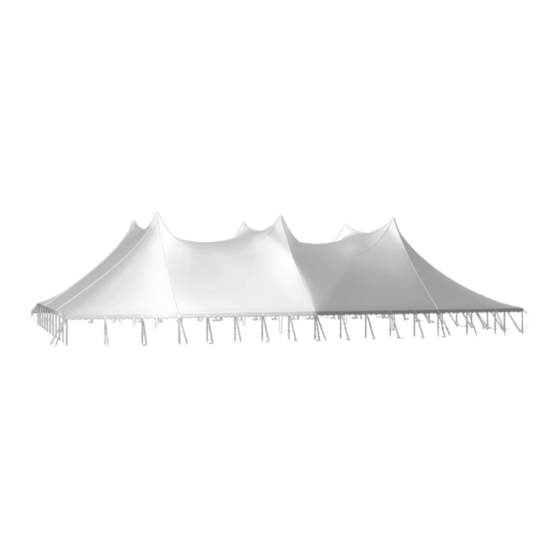
Installation Instructions
100' One-piece
Century
Tent
®
Non-Certifi ed Installation
See inside this manual for proper staking. Illustration is for concept purposes only.
Please read all assembly / installation instructions before the installation or removal of this product.
7701 Highway 41 N
Evansville, IN 47725
Phone: 812-867-2421
Fax: 812-867-1429
1-800-544-4445
email: tents@anchorinc.com
www.anchorinc.com
Cen1pc100 0515
Rev 719
EC4915
Advertisement

Subscribe to Our Youtube Channel
Related Manuals for Anchor Century 100


Summary of Contents for Anchor Century 100
- Page 1 Installation Instructions 100’ One-piece Century Tent ® Non-Certifi ed Installation See inside this manual for proper staking. Illustration is for concept purposes only. Please read all assembly / installation instructions before the installation or removal of this product. 7701 Highway 41 N Evansville, IN 47725 Phone: 812-867-2421 Fax: 812-867-1429...
-
Page 2: Parts Illustrations
The requirements as specified with blue print (supplied by Anchor Industries Inc.) must be followed. The installer/owner must read the assembly instructions com- pletely prior to any installation. Particular attention must be given to anchoring! See Caution Statement on back page of this manual. - Page 3 Parts Illustrations (cont’d) Stake line Stake driven through hole in bar and winch plate Stake driven through hole in bar and Stake line winch plate 4’ STAKE BAR 2’ STAKE BAR Bag with Fabric Section QUANTITY PER SECTION PARTS 30’ 40’...
- Page 4 1 WEB GUY LAYOUT* 100’ one-pc. (2) Ends with 30’ Mid MARK LOCATION OF STAKES, SIDE POLES & CENTER POLES 90’-0’ TENT LINE ** To find diagonal measurement: diagonal = width² + length² REQUIRED DISTANCE BETWEEN SIDE POLES AND STAKE LINES: 7’...
- Page 5 THE INSTALLER MUST USE THE LOCAL SOIL CONDITIONS TO CALCULATE THE ACTUAL NUMBER OF STAKES REQUIRED AND IS RESPONSIBLE FOR THE STAKING PATTERN AND CONFIGURATION. ANCHOR PROVIDES ANCHORING PACKAGES FOR COMMON SOIL CLASSIFICATIONS; CONTACT YOUR TENT SALES REPRESENTATIVE FOR MORE INFORMATION.
- Page 6 WEB GUY - STAKING GUIDELINES REQUIRED DISTANCE BETWEEN SIDE POLES AND STAKE LINES: 8’ POLE STAKE OUT 6’ 0” 10’ POLE STAKE OUT 7’ 6” 12’ POLE STAKE OUT 9’ 0” (1) WEB GUY (2) WEB GUYS WITH 2’...
- Page 7 TENT LAYOUT Drive stakes at points located. Each 2’ stake bar requires (3) 42” double head stakes. Each 4’ stake bar requires (6) 42” double head stakes. Spread drop cloths and unroll tent. Caution: Any objects with sharp projections which must remain on site under the tent should be padded and taped. LACING With tent sections on ground, overlap rings (or plates) at center pole holes with grommet side on top.
- Page 8 CENTER POLE TOP WELDMENT FOR “RING STYLE” CONSTRUCTION Overlapping Set top weldment in center pole hole and connect to overlap- Rings ping rings as shown. Top Weld- Place pole cap over top weldment, and push fabric and weld- ment ment up into cap and secure from underneath by threading the female coupling onto the male pipe fi...
- Page 9 Web to Winch Insert guy web loosely into slot in winch drum, approximate- ly 4’-0” for 8’-0” side pole and 1’-6” for 10’-0” side pole. Rotate drum 1 1/2 to 2 times to secure web. Repeat at all guy web locations. Raise Side Poles Start at side opposite wind.
- Page 10 CAUTION: For Tents using Center poles with No base plates, it is required to properly anchor bases of all Center poles to prevent movement after Center Poles are raised.
- Page 11 Raise Center Poles cont’d Assemble center poles with base plates (where applicable). Raise center poles with top pointing downwind. With bottom of center pole in bucket of front end loader, slowly guide top of pole under tent with installers as shown. For Ring Style construction, connect top weldment to pole with bolt, washer, and nut at center pole hole.
- Page 12 Alternate method using Pole Sled (for use with fork truck or front end loader with pallet fork attachment). Connect chain with Using the pole sled makes it possible to keep the shackles to loader to center pole steadily attached to a loader with pallet Slide forks into rect- prevent detachment.
- Page 13 Tension Guy Webs Tension webs at laces that are parallel with the width of tent fi rst and then at corners. Next, tension guy webs at middle(s). Work around the tent in a balanced manner so that tent is tensioned as evenly all around as possible. Caution - DO NOT OVER-TENSION TENT BEYOND EAVE LINE.
- Page 14 Regardless of the number of stakes we suggest, we make no representation or warranty as to whether this specifi c number of stakes will meet the local tent code. Anchor does not, nor can it make any suggestions, representation, or warranties about the adequate staking required at each specifi...
- Page 15 Caution: Do not slide closure tool over aps until aps are in- position and Maxi-grip is over-lapped. Closure tool may pop off. Care of Maxi-Grip Maxi-grip Closure Tool Anchor Industries recommends the use of 303 Aerospace Protectant for the care and maintenance of your Maxi-grip zipper Figure 3 closure system.
-
Page 16: Problem Checklist
Care of Maxi-Grip after Washing Tent After each and every Tent washing, follow these instructions: Completely rinse with plain water and wipe with sponge to remove any detergent residue. This step is critical to the • effective functionality of Maxi-Grip. •... - Page 17 MAINTENANCE, REPAIR AND REPLACEMENT OF MAXI-GRIP FLAPS Anchor’s standard warranty covers materials & workmanship for a period of 1 year from date of purchase. This does include that the Maxi-Grip will not separate during normal usage if Anchor’s installation instructions are followed.
Need help?
Do you have a question about the Century 100 and is the answer not in the manual?
Questions and answers