
Subscribe to Our Youtube Channel
Related Manuals for Woodway BOOST 2 Series


Summary of Contents for Woodway BOOST 2 Series
- Page 1 Motorized Medical BOOST 2 Treadmills BOOST 2 CORE BOOST 2 ELITE User Manual Product: BOOST 2 Document Number: UM-B2-EN-04 Revision Number: Approved By: SW/DG...
- Page 2 Manufacturer: European Representative: European Importer: WOODWAY USA, Inc. WOODWAY GmbH WOODWAY GmbH W234 N700 Busse Rd. Steinackerstr. 20 Steinackerstr. 20 Waukesha, WI 53188 79576 Weil am Rhein 79576 Weil am Rhein Germany Germany Tel.: +1 262 - 548 - 6235 Tel.: +49 (0) 7621 - 940 999 - 0...
-
Page 3: Table Of Contents
Table of Contents 1 INTRODUCTION ..............................5 1.1 O ........................5 PERATING NSTRUCTIONS NFORMATION 1.1.1 Read the Operating Instructions ......................5 1.1.2 Observe the Operating Instructions ......................5 1.2 L ............................6 IMITATION OF IABILITY 1.3 C ................................6 OPYRIGHT 1.4 R .............................. - Page 4 6.2.1 Completion of Installation ........................38 6.2.2 Safety Checklist for Before Starting Operation..................38 6.3 R ..............................38 EPLACING ARTS 6.3.1 Fuses ................................. 39 7 OPERATION ..............................42 7.1 F ..............................42 AFETY 7.2 B ..............................43 EFORE 7.3 P .............................
-
Page 5: Introduction
NOTE The BOOST 2 CORE and BOOST 2 ELITE system features the WOODWAY 4FRONT treadmill. For treadmill instructions and safety information see the WOODWAY MOTORIZED Treadmill Manual. Collectively the BOOST 2 CORE and BOOST 2 ELITE are referred to as the BOOST 2 PRODUCTS throughout this manual unless otherwise specifically identified. -
Page 6: Limitation Of Liability
The manufacturer reserves the right to make technical changes in the context of improving the performance properties and further development without prior notice. Illustrations are for basic understanding and may differ from the actual design of the device. Accessories from other suppliers have further safety regulations and guidelines which must also be observed. -
Page 7: Replacement Parts
1.4 Replacement Parts The manufacturer recommends the use of original replacement parts. Original replacement parts have particular qualities to ensure reliable and safe operation. • Developed for specific use with the device • Manufactured for high quality and excellence Ensure the legal warranty period (excluding wear parts) or other reached agreements •... -
Page 8: Electromagnetic Compatibility
E-Mail: support@boosttreadmills.com Web: boosttreadmills.com For machine service questions in the EU, contact the following: WOODWAY GmbH Steinackerstr. 20 79576 Weil am Rhein GERMANY Tel. +49 (0) 7621 - 940 999 - 14 Fax +49 (0) 7621 - 940 999 - 40 Email: service@woodway.de... -
Page 9: S Declarations For Electromagnetic Compatibility (Emc) And Associated Risks
NOTE According to CISPR 11, the BOOST 2 is a Class A device. The device can cause radio interference or disrupt the operation of equipment in the vicinity. It may be necessary to take appropriate remedial measures, such as changing the direction, realigning or shielding the device, or filtering the connection to the location. - Page 10 IEC 61000-3-3:2013 +AMD1:2017 +AMD2:2021 (Voltage fluctuations and flicker) The EMISSIONS characteristics of this equipment make it suitable for use in clinics, professional wellness facilities, and hospitals only. If it is used in a residential environment (for which CISPR 11 class B is normally required) this equipment might not offer adequate protection to radio-frequency communication services.
- Page 11 The intended use of the system is for athletic performance enhancement and the recovery of musculoskeletal injuries for those able to ambulate with body weight support. Please check with a physician to determine if you or your patient is indicated for use with these products. The limits are designed to provide reasonable protection against harmful interference in a typical hospital or commercial installation.
-
Page 12: Eu Declaration Of Conformity
1.8 EU Declaration of Conformity Product: BOOST 2 Document Number: UM-B2-EN-04 Revision Number: Approved By: SW/DG... -
Page 13: Safety
2 Safety !!!!!!!!!!!!!!! IMPORTANT - PLEASE READ !!!!!!!!!!!!! The BOOST 2 comes equipped with a safety magnet that is the primary mitigation against all motor/movement related injuries. The function of the safety magnet is to cut power to all actuators when it is pulled. This includes shutting down the treadmill belt and incline motors, shutting down the blower, and shutting down the lift motors. -
Page 14: Important Safety Instructions
!!!!!!!!!!!!!!! IMPORTANT – PLEASE READ !!!!!!!!!!!!! The BOOST 2 uses an automated lifting system to improve ingress and egress from the device. This automated lift system requires power to move. If power is removed for one reason or another (magnet is pulled, fuses blow, etc), there are release pins that may be pulled to allow the enclosure to lower for patients to exit the machine. - Page 15 Read all instructions before using the BOOST 2 DANGER: Do not operate in damp or wet locations. • • Do not operate the heart rate monitor transmitter in conjunction with an electrical heart pacemaker. The transmitter may cause electrical disturbances. Do not attempt to service your BOOST 2 products yourself without first contacting •...
- Page 16 • Keep the rear of the machine clearly marked with pinch point stickers visible. Keep Boost step at the rear of the machine to mitigate against rear pinch hazard during machine incline. WARNING To reduce the risk of injury to you and others •...
-
Page 17: Description Of Warning Notices
• Handicapped patients (e.g. fragile, patients with an intellectual disability, etc.) should never mount the BOOST2 without the help of the therapist. The therapist and attending physician must weigh the risks and benefits of using the BOOST 2. To ensure safety and maximize benefits, Boost Treadmills recommends all patients •... -
Page 18: Symbols And Signs Used On Device And In The Manual
Safety relevant information is identified on the device and in the user manual using the following symbols: Refer to instruction manual Follow the instructions for use CE label according to Regulation (EU) 2017/745 (MDR) Manufacturer WOODWAY USA, Inc. European Representative WOODWAY GmbH European Importer WOODWAY GmbH Product: BOOST 2... - Page 19 Year of construction Medical Device Mains switch (OFF/ON) Protective Ground Wire Connection Motorized treadmills are electrical devices in protection class I. Proper ground wire connection must be ensured. This notice is located inside the housing of the treadmill. Danger Due to Electric Voltage This symbol warns the user of dangerous voltage inside the device.
-
Page 20: Health Risks
Emergency Stop Indicates location of emergency stop magnet (pull-cord type) Grounding Indicates operational ground connections inside the device. Potential Equalization For the connection of a potential equalization cable This symbol is used to label electrical and electronic devices that must not be disposed of together with normal, unseparated household waste but must be treated separately. -
Page 21: Pregnancy
► The device may only be operated by persons who have received instructions from qualified service personnel. WOODWAY recommends the use of a training record ► Representative: The representative is the person or company that is responsible for setting up, using, and maintaining the device. -
Page 22: Intended Use
any person who - regardless of qualifications - independently uses the product in the commercial sector. The operator is personally responsible for the safety of the user (e.g. patient, test subject, athlete). Due to the high degree of responsibility, these people have a special obligation to provide information on all aspects of safety of the device and its intended use. -
Page 23: Essential Performance
2.7 Unauthorized Modes of Operation WARNING Unauthorized Use Can Cause Injury! Using the BOOST2 in a manner not authorized by WOODWAY can be potentially hazardous. ► Only use the device for its intended use as described in the manual. - Page 24 The BOOST 2 may only be used for the aforementioned intended use. Any additional uses may result in serious personal injury and/or property damage. The following restrictions and prohibitions must be strictly adhered to: • BOOST 2 may not be used without prior instruction by qualified personnel. •...
-
Page 25: Technical Data
3 Technical Data 3.1 Name Plate The nameplate contains the device's main technical details. For service questions, the technical information on the nameplate must be kept handy. Boost 2 Core (US) Boost 2 Elite (US) Boost 2 Core (UK) Boost 2 Elite (UK) Product: BOOST 2 Document Number:... -
Page 26: Technical Specifications
Boost 2 Core (EU) BOOST 2 ELITE (EU) 3.2 Technical Specifications BOOST 2 CORE & BOOST 2 ELITE Parameters Description Overall Dimensions 42” W x 82” L x 77” H (117 x 208 x 196 cm) Running/Walking Surface 22” W x 60” L (55 x 152 cm) Speed FORWARD SPEED Core: 12mph / 19kph... -
Page 27: Conditions For Use
Conditions for Use (operation) Temperature: 50°F to 92°F (+10°C to +33°C) Relative humidity: 30 - 85% (not condensed) Altitude: <2000m Enclosure Rating: IP20 Power Connection Grounded plug Ratings: 120 VAC ; 16A; 60Hz (BOOST 2 CORE) 200-208V VAC; 16A; 60Hz (BOOST 2 CORE & ELITE) 230V, 13A, 50/60Hz (BOOST 2 CORE) 230-240V, 16A, 50/60Hz (BOOST 2 CORE &... -
Page 28: Electrical Connection
3.4 Electrical Connection IMPORTANT: The power cord must be properly protected at all times, both when in use and in storage. IMPORTANT: Grounded receptacles are required for proper use of the BOOST 2 device. Failure to properly ground the device can lead to serious injury of the patient or operator. This product must be grounded. - Page 29 The BOOST ELITE product is for use on a nominal 200-208 circuit or 230V circuit with dedicated 20A circuit breaker in the US, and requires an outlet that looks like sketch below. EUROPEAN CONFIGURATIONS The BOOST 2 CORE and ELITE Products are for use on a 230V-240V circuit with 16A dedicated circuit breaker.
- Page 30 The BOOST 2 ELITE Products are for use on a 230V-240V circuit with 16A dedicated circuit breaker. The BOOST 2 ELITE products come equipped with a grounded plug that will require an outlet that looks like sketch below. Section 3.2 details the standard electrical requirements of the BOOST 2 machines. There are different options depending on which model you own.
- Page 31 DANGER Danger of Death by Electric Shock! Improper handling of electrical equipment by unqualified persons can cause fatal electrical shock. ► If necessary, allow only qualified personnel to perform electrical installation. ► The power cord must not come into contact with hot surfaces or sharp edges.
-
Page 32: Transportation And Storage
4 Transportation and Storage 4.1 Safety Notices for Transportation Check the BOOST 2 for damage upon arrival. Also check and compare supplied accessories with the corresponding delivery note. The manufacturer is not liable for damages and missing parts if this information was not recorded in writing on the delivery note upon delivery of the unit. - Page 33 See the BOOST 2 Service Manual for additional information. Product: BOOST 2 Document Number: UM-B2-EN-04 Revision Number: Approved By: SW/DG...
-
Page 34: Product Description
5 Product Description See the following sections for a detailed description of the operation. WARNING Risk of Injury Through Falling! During training, especially during the initial use of the device, there is a danger of injury from falling. Only transport in compliance with the safety regulations. -
Page 35: Boost 2 Enclosure
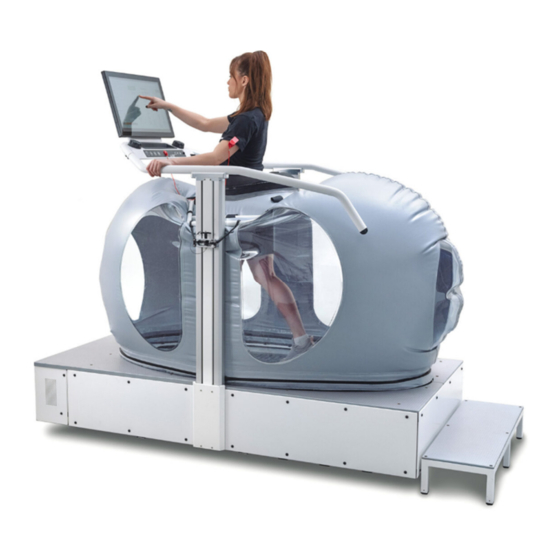
5.1 BOOST 2 Enclosure The fabric enclosure, or enclosure, surrounds the BOOST 2 and holds air pressure. It is made of an extremely durable and strong vinyl reinforced fabric with vinyl windows. The enclosure is designed to be stepped on when entering or exiting the BOOST 2. The enclosure can be cleaned with a normal surface cleaner that you would use to items such as training tables, glass, etc. -
Page 36: Air-Pressure System
NOTE Shorts included with the purchase of a system come with a 90-day warranty. 5.3 Air-Pressure System The air-pressure system is designed to create specific lift amounts on each individual user. The system measures both the inside and outside air pressure many times per second and is constantly adjusting to allow for comfortable and consistent use. -
Page 37: Setup & Installation
6 Setup & Installation 6.1 General Ensure that the conditions applicable to basic safety and health requirements are met. Read these operating instructions and the BOOST 2 installation manual completely before the installation of your BOOST 2. Before installing the device, operational and functional safety are to be tested, including correct installation, electrical connection, and operator instruction. -
Page 38: Completion Of Installation
► Prepare a stable and sturdy surface. ► Only install the device on a level, stable, and sufficiently sturdy surface. ► If necessary, install an additional base plate/floorboard. 6.2.1 Completion of Installation Prior to starting operation, installation is to be completed with a trial run. During the trial run, all device functions are to be carried out and checked. -
Page 39: Fuses
The location and instructions for changing the fuses in the Boost 2 are listed below. WOODWAY FUSES The fuses on the woodway base are located on the AC bracket behind the front-right hand side panel of the Boost. Ensure Boost 2 is powered down. To remove the fuses, push in and make a quarter turn to the left, then remove pressure and they will release. - Page 40 BLOWER BOARD FUSES The fuses on the blower board are located in the blower box at the front of the Boost 2. Ensure the Boost 2 is powered down. To remove the fuses, pry them out of the fuse holders with a screwdriver.
- Page 41 Ensure the Boost 2 is powered down. To remove the fuses, remove the plastic fuse covers and pry them out of the fuse holders with a screwdriver. When replacing, ensure you have glass fuses, 4A 250V AC DC 5mm x 20mm (Bel Fuse PN 5ST 4-R). Insert the fuses back into the fuse holders by inserting one side, and then applying pressure to the other side until they click into place.
-
Page 42: Operation
7 Operation WARNING Danger Through Uncontrolled Running Surface Movement! By stepping on the rear-most part of the running surface where it is rounded, the force of gravity can set the running surface in motion. There is danger of falling. Ensure that the user does not step on the rounded part of the ►... -
Page 43: Before Each Use
NOTE The user/owner or representative of the equipment is responsible for ensuring that regular maintenance and inspection of the BOOST 2 is carried out. Defective components must be replaced immediately. The BOOST 2 should not be used until it is repaired by a professional. 7.2 Before Each Use Before the unit is put into operation, the following checks are to be performed: Inspect running surface belt (look for dirt and damage to slats) -
Page 44: Practical Training
Enclosure and shorts integrity (leaks, cuts, or any other damage) Fall protection equipment e.g. hand-rail WARNING Danger of Being Pulled into Moving Parts! In the event of a fall, people with long hair, loose clothing or jewelry can be pulled into running surface entry points. ►... -
Page 45: Proper Body Form
7.3.3 Proper Body Form When running or walking, it is important to maintain proper form to maximize efficiency and results and minimize the possibility of personal injury. Keep your posture upright; avoid leaning forwards or backwards from the waist, as this can cause unnecessary back strain and decrease your efficiency. -
Page 46: Instructions For Use
7.4 Instructions for Use Body weight dial Speed dial Estop Magnet PAUSE Incline HR Receiver START STOP Magnet Clip Cupholder BOOST 2 Display, Buttons, and Dials 7.4.1 Powering On/Off the BOOST 2 On the front face of the BOOST 2 device adjacent to the power cord entry is the On/Off switch. -
Page 47: Boost 2 Entry
7.4.2 BOOST 2 Entry Select the proper short size and put the shorts on with the Boost logo on the left quadricep. The shorts should be snug around a user’s thighs and waist, but comfortable enough for exercise. Product: BOOST 2 Document Number: UM-B2-EN-04 Revision Number:... - Page 48 The following table will help you choose the right shorts size Wear form fitting clothes such as athletic leggings or small shorts underneath to ensure that the Boost shorts remain tight over multiple uses. Remove all objects from pockets, especially sharp or pointed objects, to avoid injuries or pressure points. Remove shoes prior to putting the shorts on.
-
Page 49: Setup
7.4.3 Setup Use the “Sign in or Register” or “Start without Logging in” buttons to set up a workout, then select your height and shorts size. Confirm your information and then allow the carriage to raise to the proper height using the “Confirm” button on the screen. Zip the shorts into the enclosure. -
Page 50: Starting Workout
The height of the enclosure is selected based on the input user height. The user height should have been selected before zipping the shorts into the enclosure. For lateral movement, use the zipper on the right side of the shorts to zip into the enclosure. - Page 51 The red stop button finishes the workout, deflates the enclosure, and stops the treadmill. The yellow pause button pauses the workout, deflates the enclosure, and stops the treadmill. The start button inflates the enclosure to desired body weight percentage after pausing the workout.
- Page 52 Reverse Mode and Free Run Mode can be accessed using the buttons in the top right of the workout screen. The red magnet is the emergency stop. The clip attached to it MUST be attached to the user during operation. Once the magnet is removed, the enclosure will be deflated, and the treadmill will stop.
-
Page 53: Completing Workout
7.4.5 Completing Workout Turn the speed dial down to zero and lower the incline to zero Hit the square stop button and then press ‘Finish’ on the bottom right corner of the screen. Select “Exit”. Once the enclosure has deflated, unzip the shorts from the machine while keeping them on. -
Page 54: Emergency Exit, Removing Seal Frame From Lifts
Once the shorts are unzipped, confirm so on the screen and the lifts will lower. When the enclosure is lowered to about 22 inches, the machine will display a prompt to make sure everything is clear of the lift before the lift lowers the rest of the way. Step out of the machine. - Page 55 Allow the seal frame and enclosure to drop to the floor, manually push any fabric out of the way that may impede a user’s egress from the machine. Instruct the user to exit the machine carefully. In order to reconnect the seal frame and enclosure to lift columns: Troubleshoot or restore power to lower the lift columns to the base (perhaps requiring a reset of the power).
-
Page 56: Cleaning And Maintenance
► It is the sole responsibility of the representative to assign qualified personnel for maintenance and repair work. ► In case of doubt or questions, always contact the WOODWAY customer service or dealer! The manufacturer is not liable for personal injury and material ►... -
Page 57: Cleaning Notes
DANGER Danger of Death by Electric Shock! The use of water and liquid detergents as part of cleaning work can cause serious or fatal electrical shock. ► No liquids may come in contact with electrical parts such as motor, power cord and power switch, control monitors. ►... -
Page 58: Lift Column
NOTE Boost Shorts must be cleaned strictly according to provided instructions. Using unauthorized cleaners and processes can cause rapid degradation of shorts material and cause leaking of shorts and lead to machine errors. Contact Boost service with any questions. 8.1.3 Lift Column The lift column should be checked periodically by a technician. -
Page 59: Maintenance Intervals
8.2 Maintenance Intervals The BOOST 2 must be maintained properly in order to extend the lifetime of the machine and to ensure user safety. It is recommended that the customer have a professional preventative maintenance service done annually by the company. Regular Maintenance On a regular basis (weekly recommended), inspect the following components for damage, wear, or requiring attention otherwise) -
Page 60: Functional Test
DANGER Danger of Death by Electric Shock! Maintenance and inspection work on the unit may cause serious or fatal electrical shock. Pull power plug prior to any maintenance and inspection work ► on the equipment. The device must not be connected to power! Ensure the device cannot be switched back on. -
Page 61: Immediate Service
Does the lift bring the enclosure up to the proper height displayed on the screen? Operate the display to provide air pressure. Straddle the running surface for the remaining steps below (Feet on side covers; not running). Turn up the treadmill to maximum speed for a short time. Does the treadmill reach the specified max. -
Page 62: Disabling The Boost 2
Damage to the running surface belt. Hole in the enclosure. Cracking in any welding joints. All other defects which may affect the safety of the device. 8.3 Disabling the BOOST 2 Disabling is required if the safety of the BOOST 2 is not guaranteed or if it is suggested that this could be the case. - Page 63 - may start up the BOOST 2 again. The fuses must be removed from the power supply box in the Woodway 4 Front base and kept in a safe place. Attach one of the following safety labels to the BOOST 2 power supply fuse box.
-
Page 64: Troubleshooting
Sample Label for Disabling a BOOST 2: ATTENTION DANGER OF INJURY! This device has been disabled due to safety defects. The use of this device is strictly forbidden. Device was disabled on: ____________________ by: ____________________________________ Only the following person may put this device back into operation: ___________________________________________ 9 Troubleshooting... -
Page 65: Device Lifetime
10 Device Lifetime The service life of this device is 7 years. Warranty Information Boost warrants that all products and accessories will be free from manufacturing defects according to the applications/terms listed above. The warranty period commences on the original date of purchase (with the exception of the running belt component, which is warranted for a period of four (4) years from the original date of purchase). -
Page 66: Maintenance Report
11 Maintenance Report Product: BOOST 2 Document Number: UM-B2-EN-04 Revision Number: Approved By: SW/DG... -
Page 67: Record Of Instruction
(users) must be included in the instruction procedure. Once the initial operation and instruction has taken place, the instruction protocol must be signed by the instructor and all those instructed, and a copy sent back to Boost/WOODWAY. Step... - Page 68 Step Description Conducted Instruction on Initialization Phase. After turning on the Boost, the device goes through a start phase, which lasts about 30-40 seconds. User/patient should not get on the treadmill during the start phase. Then the lift columns must me initialized before the treadmill ...
- Page 69 When cleaning the unit always pull the power plug before the start. Maintenance and repair of medical devices and electrical equipment only by authorized personnel (Boost/WOODWAY service technicians, authorized Boost/WOODWAY service partner or medical technician). Notice on regular and recurring maintenance intervals with regard to safety checks in Section 8 of the User Manual.
- Page 70 Please fill out the instruction protocol completely and send it back to Boost/WOODWAY. Product: BOOST 2...
- Page 71 Boost 2 (using WOODWAY treadmill) Serial no.: ____________________________ Model: ___Boost 2___________________ Technical instruction was completed on: _________________________ (Date) Technical instruction took place on: __________________________ (Date) Place of transfer / instruction: _________________________________________________________ __________________________________________________________ __________________________________________________________ The following persons received instructions: _______________________________________ _______________________________________...
-
Page 72: Disposal
13 Disposal The disposal of the equipment must be in accordance with the respective national regulations. Electrical and electronic devices must be disposed of separately from normal household waste. An appropriate waste disposal company should be contacted. Properly dispose of the device at the end of its service life (e.g.
Need help?
Do you have a question about the BOOST 2 Series and is the answer not in the manual?
Questions and answers