Woodway 4Front Operating Manual
Slat-belt treadmills sports & fitness
Hide thumbs
Also See for 4Front:
- User manual (136 pages) ,
- Translation of the original operation manual (110 pages) ,
- Service manual (97 pages)

Related Manuals for Woodway 4Front


Summary of Contents for Woodway 4Front
- Page 1 Slat-belt Treadmills Sports & Fitness Includes the models: 4Front Desmo Mercury Path Pro XL Translation of the original German Operating Manual Version: 02/2014-v1.0en...
- Page 2 European Representative: Manufacturer: WOODWAY GmbH WOODWAY USA, Inc. Steinackerstr. 20 W229 N591 Foster Ct. 79576 Weil am Rhein Waukesha, WI 53186 Germany Tel.: +49-7621-940 999-0 Tel.: +1-262-548-6235 Fax.: +49-7621-940 999-40 Fax.: +1-262-522-6235 E-mail: info@woodway.de E-mail: info@woodway.com Web: www.woodway.de Web: www.woodway.com Sales: Tel.
-
Page 3: Table Of Contents
RS-232 Interface ................ 15 Technical Specifications .............. 16 3.3.1 Desmo / Desmo H / Desmo HP ......... 16 3.3.2 4Front / 4Front with TV ............ 17 3.3.3 Mercury / Mercury H ............18 3.3.4 Path / Path H ..............19 3.3.5 Pro / Pro XL.............. - Page 4 7.7.8 Program Options ............. 68 Options ....................69 Power Input 208 / 230 V ............69 Control Element in the Railing ............. 69 TV Setting, 4Front ..............69 Maintenance and Cleaning ..............71 Cleaning ..................71 Maintenance Intervals ..............72 Lubrication ................
-
Page 5: Introduction
Use of replacement parts which were not approved by WOODWAY. Unauthorized modifications to the device or accessories. WOODWAY GmbH general terms and conditions and delivery conditions apply, as well as the legal regulations valid at the time of contract conclusion. 02/2014-v1.0en... -
Page 6: Copyright
NOTE The use of NON-original replacement parts may change the characteristics of the device and interfere with the safe use! WOODWAY does not accept liability for damages resulting from this. Disposal! Wear parts are considered hazardous waste! After being replaced wear parts must be disposed of according to country-specific waste laws. -
Page 7: Customer Service
Introduction Customer Service For service questions contact the following: WOODWAY GmbH Steinackerstr. 20 79576 Weil am Rhein Germany Contact: Tel. +49 (0) 7621-940999-14 Fax. +49 (0) 7621-940999-40 Email: service@woodway.de For faster processing of your request please have the following data and infor- mation available: ... -
Page 8: Ec Declaration Of Conformity
Introduction EC Declaration of Conformity Fig. 1 EC Declaration of Conformity 02/2014-v1.0en... -
Page 9: Safety
Warnings attached directly to the device must be observed and kept in a legible condition. Inappropriate use will result in the rejection of any liability or guarantee claims by WOODWAY. Description of Warning Notices Warning notices indicate potential hazards or safety risks. They are indicated in this manual by a color-coded signal word panel (symbol with the appropriate signal word). -
Page 10: Safety Notices On Device
Safety Safety Notices on Device The treadmills are equipped with the following listed safety markings. Safety rele- vant information is identified using the following stickers: 2.3.1 Desmo / Mercury / Path / Pro / Pro XL Protective Ground Wire Connection Motorized treadmills are electric devices in protection class I. -
Page 11: 4Front
To prevent injury, stand on the side panels prior to starting the device. Read the operating instructions prior to use. 2.3.2 4Front Protective Ground Wire Connection Motorized treadmills are electric devices in protection class I. Proper ground wire connection must be ensured. -
Page 12: Health Risks
Safety Notice on Display 4Front Left Side! To prevent injury, stand on the side panels prior to starting the device. Read the operating instructions prior to use. Consult your trainer/therapist prior to use. Stop training immediately if you feel dizzy or exhausted. -
Page 13: Intended Use
The operating instructions are an integral part of the treadmill and are to be availa- ble to all users at all times. The exact observance of the instructions is a prerequi- site for the intended use of the WOODWAY treadmill. WARNING Risk of Injury Through Risk of Falling! The motorized treadmill presents the danger of falling. -
Page 14: Unauthorized Modes Of Operation
It is forbidden to use the treadmill without its side rails or with walking poles. The operation of WOODWAY slat-belt treadmills outside of the named ambient conditions in the section "Commissioning" (temperature, humidity, air pres- sure) as well as outdoors, i.e. outside of closed rooms is not allowed. -
Page 15: Technical Data
Technical Data Name Plate Each WOODWAY treadmill receives a serial number during production. Depending on the year of your model, it has an alphanumeric code with 7-8 characters or a numeric code with 9 digits. The serial number can be found on the name plate, which is mounted on the rear of the display or on the left front of the treadmill frame. -
Page 16: Technical Specifications
Technical Data Technical Specifications 3.3.1 Desmo / Desmo H / Desmo HP Desmo Running Surface: 173 cm x 55 cm. Usable surface: 157 cm x 55 cm. Speed: 0 - 20 km/h. Incline: 0 - 15%. ... -
Page 17: 4Front / 4Front With Tv
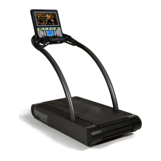
Technical Data 3.3.2 4Front / 4Front with TV 4Front Running Surface: 173 cm x 55 cm. Usable surface: 157 cm x 55 cm. Overall dimensions (standard display): Width 89 cm Length 183 cm Height 163 cm Weight: 201 kg. -
Page 18: Mercury / Mercury H
Technical Data 3.3.3 Mercury / Mercury H Mercury Running Surface: 173 x 43 cm Usable surface: 157 cm x 43 cm. Speed: 0 - 17 km/h. Incline: 0 - 15%. Total dimensions: Width 86 cm Length 180 cm Height 152 cm ... -
Page 19: Path / Path H
Technical Data 3.3.4 Path / Path H Path Running Surface: 132 x 55 cm. Usable surface: 120 cm x 55 cm. Speed: 0 - 17 km/h. Incline: 0 - 15%. Total dimensions: Width 97 cm Length 150 cm Height 152 cm ... -
Page 20: Pro / Pro Xl
Technical Data 3.3.5 Pro / Pro XL Running Surface: 173 cm x 70 cm. Usable surface: 157 cm x 70 cm. Speed: 0 - 25 km/h. Incline: 0 - 25%. Total dimensions: Width 122 cm Length 196 cm Height 173 cm ... -
Page 21: Running Surface
Running area see respective treadmill type Standard color Black Storage Desmo/4Front/Mercury/Path/Pro = 114 ball bearings, 12 guide rollers Pro XL = 160 bearings, 18 rollers Path = 64 bearings, 8 rollers Lateral movement +/- 8 mm/h Conditions for Use... -
Page 22: Transportation And Storage
The manufacturer is not liable for damages and missing parts if this information was not recorded in writing on the delivery note upon delivery of the unit. Damage or defects must be reported to the carrier and to the responsible WOODWAY dealer immediately. -
Page 23: Storage
Transportation and Storage Storage The device may only be stored in closed, dry rooms. It is absolutely necessary to prevent contact with moisture (rain, fog, etc.) The following environmental conditions are prescribed for transportation and stor- age: Temperature: -18°C to +49°C. ... -
Page 24: Product Description
WOODWAY treadmill you may initially notice higher surface grip than you have ex- perienced before. The more you use your treadmill, the more you will get used to the grip. As with all treadmills, it is also important on a WOODWAY treadmill not to shuffle your feet if possible. -
Page 25: Incline System
Product Description Incline System WOODWAY treadmills are equipped with a standard elevation system up to 15% (with variations between -3 and +22%, and between 0 and +25%). The elevation system is controlled driven by a geared motor and a chain drive system which is used to transmit forces to several drive sprockets. -
Page 26: Commissioning
Commissioning Commissioning General Commissioning is the initial intended use of the device, see sec. 2.5 Page 13. En- sure that the conditions applicable to basic safety and health requirements are met. Read these operating instructions completely before commissioning. Before commissioning the device, operating and functional safety is to be tested. This includes correct installation and operator instruction. -
Page 27: Assembly Instructions
The treadmill can be delivered in various states of assembly. Disassembly / assem- bly may be required for moves or relocation into other rooms. NOTE In WOODWAY sports treadmills standard (inch) screws and nuts are used, with few exceptions. These are not compatible with metric fastening elements! -
Page 28: Desmo
Commissioning 6.3.2 Desmo Tools required for assembly: 1 x Phillips head screwdriver, size 1. 1 x Phillips head screwdriver, size 2. 1 box wrench SW 13. - Insert the railing tube into the mounts on both sides. - Observe hand protection! Fig. -
Page 29: Fig. 7 Desmo Assembly, Electronic Cover Plate
Commissioning - Remove electronic cover plate on the right side of the treadmill frame (Phillips screw driver). Fig. 7 Desmo Assembly, Electronic Cover Plate - Lay the wire through the hole in the console. Fig. 8 Desmo Assembly, Connection 1 - Attach the protective conductor (green) to the contact tab on the housing. -
Page 30: Fig. 11 Desmo Assembly, Connection 4
Commissioning - Fix the wires to the frame with the supplied wire ties. - Then remount the electronic cover plate. Fig. 11 Desmo Assembly, Connection 4 - Slide the side covers onto the left and right sides. - Guide the covers, slightly tilted under the rubber railing covers. -
Page 31: 4Front
1x Phillips screwdriver PH1. - Remove the covers on the left and right. Fig. 14 4Front Assembly, Side Panel - Insert wire and protective cover into the guard rail tube to prevent damage during insertion. Fig. 15 4Front Assembly, Wiring - Prepare the mount for the tube. -
Page 32: Fig. 17 4Front Assembly, Inserting Tubes
- Insert the railing tube into the mounts. - Do not damage the wires! - Observe hand protection! Fig. 17 4Front Assembly, Inserting Tubes - Pull the wire and protective cover out of the railing tube. Fig. 18 4Front Assembly, Connection 1 - Lay the wire with protective cover behind the railing mount. -
Page 33: Mercury, Path
Commissioning - Tighten railing mount bolts. Fig. 21 4Front Assembly, Fixing the Railing - Replace the side panels, right and left and fix them with screws. Fig. 22 4Front Assembly, Side Panel 6.3.4 Mercury, Path Tools required for assembly: ... -
Page 34: Fig. 24 Mercury/Path Assembly, Electronic Cover Plate
Commissioning - Remove electronic cover plate on the right side of the treadmill frame. Fig. 24 Mercury/Path Assembly, Electronic Cover Plate - Insert wire and protective cover into the guard rail tube to prevent damage during insertion. Fig. 25 Mercury/Path Assembly, Wiring - Prepare the mount for the tube. -
Page 35: Fig. 28 Mercury/Path Assembly, Connection 1
Commissioning - Pull wire and protective cover out of the railing tube (hole in railing tube). Fig. 28 Mercury/Path Assembly, Connection 1 - Lay the wire with protective cover through the hole in the console. Fig. 29 Mercury/Path Assembly, Connection 2 - Attach the protective conductor (green) to the contact tab on the housing. -
Page 36: Fig. 32 Mercury/Path Assembly, Fixing The Railing
Commissioning - Tighten railing mount bolts. Fig. 32 Mercury/Path Assembly, Fixing the Railing - Replace electronic cover plate on the right side of the treadmill frame. Fig. 33 Mercury/Path Assembly, Electronic Cover Plate - Slide the side covers on both sides and fix with screws (do not tighten the screws yet). -
Page 37: Pro, Pro Xl
Commissioning 6.3.5 Pro, Pro XL Tools required for assembly: 1x combination wrench SW13. 1x SW13 ratchet wrench. 1x Phillips screwdriver PH1. 1x Phillips screwdriver PH2. 1x Allen key SW8. - Insert both sides of the railing into the mounts. - First slide the cover plates over the railing. -
Page 38: Fig. 39 Pro/Proxl Assembly, Connection 1
Commissioning - Pull the wire and wire protection out of the side of the railing tube and lay it along the railing mount to the circuit board. Fig. 39 Pro/ProXL Assembly, Connection 1 - Attach the protective conductor (green) to the contact tab on the housing. -
Page 39: Fig. 43 Pro/Proxl Assembly, Fixing The Railing 2
Commissioning - Tighten railing mount bolts on the left side. Fig. 43 Pro/ProXL Assembly, Fixing the Railing 2 - Slide the side covers on both sides and fix with screws (do not tighten the screws yet). Note: First tighten the large screws, then the rest of the screws. -
Page 40: Operation
Operation Operation For Your Safety NOTE CONSULT A DOCTOR! If you are over 40 years old, have a heart condition, are overweight or have not been involved in sports for several years, a visit to the doctor is recom- mended before beginning an intensive training program. For safe operation and successful training please read the following points for your own safety before starting to use the treadmill: ... -
Page 41: Safety Equipment
► Clarification and elimination of causes of the dangerous situations only by WOODWAY Customer Service. ► Only restart the device after approval by WOODWAY customer service. 7.2.1 Safety Railing The treadmill is equipped with a railing that extends along both sides and is bowed around the front. -
Page 42: Belt Drive Current Limiter
Operation This safety feature serves to protect the user should they lose their balance or in an emergency. The plastic clip is to be fixed to the waistband when the treadmill is used. When the magnet (trigger) is removed, the drive motor is switched off and the running surface stops. -
Page 43: Practical Training
For optimal use and safety during treadmill training, WOODWAY recommends run- ning on the treadmill in an upright and natural running position and to avoid drag- ging foot movement. -
Page 44: Heart Rate Chart
Operation 7.3.5 Heart Rate Chart Maximum 60% of the 75% of the 85% of the heart rate maximum heart maximum heart maximum heart [BPM*] rate rate rate [BPM*] [BPM*] [BPM*] * BPM: Beats per minute, source: American College of Sports Medicine 7.3.6 Training Frequency At the beginning of training allow yourself enough time to get into shape. -
Page 45: Polar ® Heart Rate Monitor
Operation ® Polar Heart Rate Monitor ® The display was designed so that the user's heart rate is indicated when a Polar measuring device is used. In order to display the user's heart rate accurately on the screen, the built-in receiver display must receive a stable heart rate signal from the ®... -
Page 46: Transmitter Function
Operation Positioning: The transmitter should be positioned so that it is below the pectoralis (chest mus- cle) at sternum height (breastbone), logo to the outside. Moisten the contact sur- face of the transmitter in order to transmit the best signal possible from the body to the measuring device. -
Page 47: Display Parameters
Operation Fig. 46 Standard Display l Fig. 47 Standard Display ll Fig. 48 Standard Display lll 7.6.1 Display Parameters Manual SPEED and INCLINE control. Statistics display: DISTANCE, CALORIES, TIME, TIME/1000m, PULSE, METS. Treadmill SPEED and INCLINE display. ... -
Page 48: Starting The Help Program
Operation 7.6.2 Starting the Help Program First, check that the emergency stop magnet is in place. To switch the display on, press the "ON" key. A "0" is displayed in the speed and incline indicators. If the dis- play is not lit, ensure that the treadmill is connected to the power supply and that the power switch is turned on. -
Page 49: Personal Trainer Display
Operation INCLINE: The incline display is used to show the user's current incline or to set the incline. Valid incline values start at 0 and increase in steps of 0.1% to the maximum level of incline, which varies depending on the model and the associated options. Personal Trainer Display The keys in the display fields allow the user to type command parameters to control treadmill operation. -
Page 50: Fig. 51 Personal Trainer Display Lll
Operation Fig. 51 Personal Trainer Display lll In the LCD display with a resolution of 320 x 240 pixels, the user's program selec- tion profile and the progress during training are shown. With the program profiles the speed and incline curves are shown in charts. ®... -
Page 51: Description Of Display Elements
Operation 7.7.1 Description of Display Elements TIME: The time is displayed in 00:00 format. In the user defined mode, the time is count- ed from zero. In the program modes the time is counted down. SPEED: The speed is displayed in 00.0 format. SPEED represents the user's current speed in kilometers per hour, or it may be used to set the user's target speed. -
Page 52: Starting A Training Program
Operation The user course is laid out as shown in the following figure: Fig. 52 User Defined Track Interrupting the When the user presses the PAUSE key the treadmill stops. The following information Training is shown on the LCD display: "PAUSE - CONTINUE: PRESS PAUSE" The statistics are stopped with the pressing of the PAUSE key. -
Page 53: Fitness Programs
Operation Usable Variables While the program is running the user can change the incline using the incline keys UP and DOWN, and the speed using the speed keys FAST and SLOW. The user can interrupt the training at any time by pressing the PAUSE key. The status of the pro- gram you are in lights up to show your progress. -
Page 54: Fig. 54 Fitness Program - Weight Loss
Operation Weight Loss A program with a constant load, and gradual warm-up and cool-down phases. This Program program is designed to provide exercise at a constant level. Fig. 54 Fitness Program - Weight Loss 02/2014-v1.0en... -
Page 55: Fig. 55 Fitness Program - Aerobic
Operation Aerobic Program High level training with three very intense phases. This program is designed to improve the aerobic condition. Fig. 55 Fitness Program - Aerobic Interval Program This interval program consists of interval 1 and interval 2. Speed and incline must be entered in each interval (using the number keys or the FAST/SLOW key). -
Page 56: Fig. 56 Fitness Program - Random
Operation Random Program An interesting and challenging training program. Varying speed and incline changes are selected at random intervals. Fig. 56 Fitness Program - Random 02/2014-v1.0en... -
Page 57: Fig. 57 Fitness Program - Endurance
Operation Endurance Program A program with increasing load and two different phases, each with a peak load. Fig. 57 Fitness Program - Endurance 02/2014-v1.0en... -
Page 58: Fig. 58 Fitness Program - 5000 Meter
Operation 5000 Meter Program This program is a distance-based program with a simulated 5 kilometer race track. The user determines the running speed by selecting an intensity level. Fig. 58 Fitness Program - 5000 Meter 02/2014-v1.0en... -
Page 59: Fig. 59 Fitness Program - 10,000 Meter
Operation 10,000 Meter This program is a distance-based program with which a 10 kilometer run can be Program simulated. These programs build endurance. Fig. 59 Fitness Program - 10,000 Meter 02/2014-v1.0en... -
Page 60: Fig. 60 Fitness Program - Increasing
Operation Increasing Program A program with a slowly increasing load. Here you will gradually increase to the top speed for the selected intensity level. Then a cool-down phase begins. Fig. 60 Fitness Program - Increasing 02/2014-v1.0en... -
Page 61: Further Programs
Operation 7.7.6 Further Programs Balke Program This program is designed to determine the user's current fitness level. Using the Balke protocol this program evaluates the functional aerobic capacity (VO2max), with which the cardiorespiratory fitness of the user is determined. Under an increas- ing load, the oxygen consumption (VO2) eventually reaches a plateau. - Page 62 Operation Gerkin Program With the Gerkin protocol there is a tiered VO2 test with submaximal values. It is used by the International Association of Fire Fighters to determine fitness for ser- vice with the fire department. Set the values for your age and sex using the number keys or the FAST/SLOW key. Scroll to change fields.
- Page 63 Operation Heart Speed INCLINE PHASE MINUTE rate (km/h) (last 15 seconds of the phase) Warm-up 3 minutes Cool-down 1 minute PHASE TIME CALCULATED VO 2max 1:00 31:15 1:15 32:55 1:30 33:6 1:45 34:65 2:00 35:35 2:15 37:45 2:30 39:55 2:45 41:30 3:00 43:4...
- Page 64 Operation Cooper Program Set the values for your age and sex using the number keys or the FAST/SLOW key. Scroll to change fields. Press ENTER to start the program. Run as far as you can in 12 minutes. TO ACHIEVE AN OPTIMAL RESULT THE SPEED MUST BE ADAPTED DURING THIS TEST: Leave the incline at 0%.
- Page 65 Operation Rockport Program Set the values for your age and sex using the number keys or the FAST/SLOW key. Scroll to change fields. Press ENTER to start the program. Walk 1609 meters (one mile) as fast as you can. TO ACHIEVE AN OPTIMAL RESULT THE SPEED MUST BE ADAPTED DURING THIS TEST: Leave the incline at 0%.
-
Page 66: Automatic Pulse Programs
Operation 7.7.7 Automatic Pulse Programs Basics NOTE The automatic pulse programs can only work effectively if you wear a chest strap for heart rate measurement! When the automatic pulse program has been selected the user is prompted to enter their age, target heart rate, maximum speed, maximum time and weight on the initial screen. - Page 67 Operation Pulse control Only one of the automatic pulse types can be used during training. The user selects his desired algorithm during program setup. Automatic Pulse - This automatic pulse program only controls the incline. The user selects the speed Only Incline themselves.
-
Page 68: Program Options
Operation 7.7.8 Program Options Changing Programs During Training Simply press the FITNESS PROGRAMS key (or any other button in the menu) left on the screen to bring up the main menu and make another selection. Programing User Programs 100 user program profiles are available. -
Page 69: Options
Options Power Input 208 / 230 V The input voltage requirements of 208 and 230 V AC are versions for all WOODWAY treadmills. An input power transformer for 208 V AC or 230 V AC has been installed and connected. This does not affect the other parts of the treadmill. -
Page 70: Fig. 62 Tv Settings
Options Fig. 62 TV Settings For automatic channel setting press the "VOL +" key to enter the channel. Press the "CH -" key to scroll through the settings. Next select "Automatic tuning". Fig. 63 TV Channel Search Selection Press the "VOL +" key again for channel search. Fig. -
Page 71: Maintenance And Cleaning
► It is the sole responsibility of the representative to assign qualified person- nel for maintenance and repair work. ► In case of doubt or questions, always contact WOODWAY customer service or your dealer! ► The manufacturer is not liable for personal injury and material damage... -
Page 72: Maintenance Intervals
Maintenance and Cleaning Maintenance Intervals DANGER Danger of death by electric shock! Maintenance and inspection work on the unit may cause serious or fatal elec- trical shock. ► Pull the power plug prior to any maintenance and inspection work on the equipment. -
Page 73: Lubrication
Maintenance and Cleaning Lubrication 9.3.1 Bearings Almost all bearings in the treadmill have been lubricated by the manufacturer and must not be greased. The four (4) bearings at the front and rear axle must be lubri- cated once a year with one stroke of the grease gun. Fig. -
Page 74: Toothed Belts
Toothed Belts Incline System The incline systems on WOODWAY treadmills are lubricated by the manufacturer. The system must be checked when used over several hours or in a very dusty envi- ronment. If required, apply a small amount of lubricant to the chain and the incline drive racks. -
Page 75: Adjusting And Calibrating
Adjusting and Calibrating Incline System The incline system with toothed rack and gear drive is used on WOODWAY tread- mills. For systems with an incline of 15% to 25% similar components are used. They only differ with respect to the movement of the toothed rack. - Page 76 Maintenance and Cleaning Running Surface Does Not Move Is the safety magnet activated? Does the display function properly? If the display and/or the incline are working, unplug the treadmill and wait at least 60 seconds before reconnecting it to a power supply. RUNNING SURFACE BELT IS STUCK / IS HARD TO MOVE ...
-
Page 77: Disposal Notice
Disposal Notice Disposal Notice Electrical and electronic devices must be disposed of separately from normal house- hold waste. An appropriate waste disposal company should be contacted. Properly dispose of the device at the end of its service life (e.g. the local collection point for waste sep- aration): ... -
Page 78: Maintenance Report
Maintenance Report Maintenance Report DATE MAINTENANCE MEASURES FROM REMARKS 02/2014-v1.0en... -
Page 79: Table Of Figures
Fig. 19 4Front Assembly, Connection 2 ............32 Fig. 20 4Front Assembly, Connection 3 ............32 Fig. 21 4Front Assembly, Fixing the Railing ............ 33 Fig. 22 4Front Assembly, Side Panel .............. 33 Fig. 23 Mercury/Path Assembly, Side Covers ..........33 Fig. - Page 80 Table of Figures Fig. 54 Fitness Program - Weight Loss ............54 Fig. 55 Fitness Program - Aerobic ..............55 Fig. 56 Fitness Program - Random ..............56 Fig. 57 Fitness Program - Endurance ............. 57 Fig. 58 Fitness Program - 5000 Meter ............58 Fig.
Need help?
Do you have a question about the 4Front and is the answer not in the manual?
Questions and answers