Woodway 4Front Translation Of The Original Operation Manual
Motorized sports & fitness treadmills
Hide thumbs
Also See for 4Front:
- User manual (136 pages) ,
- Service manual (97 pages) ,
- Operating manual (80 pages)

Subscribe to Our Youtube Channel
Related Manuals for Woodway 4Front


Summary of Contents for Woodway 4Front
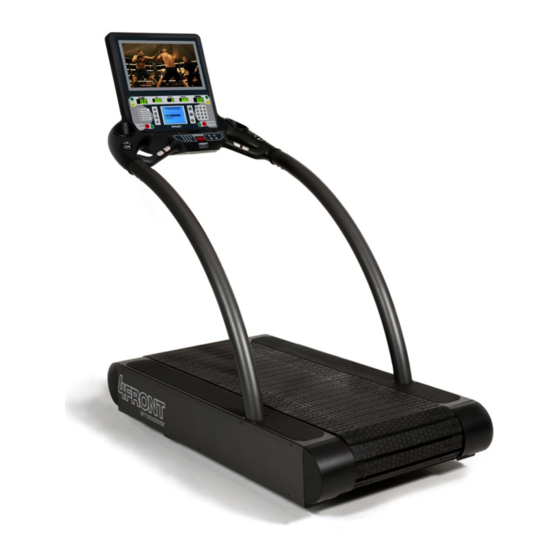
- Page 1 Motorized Sports & Fitness Treadmills Includes the models: 4Front Mercury Path Pro XL Translation of the original German Operating Manual Version: 06/2019-v2.1en...
- Page 2 European Representative: Manufacturer: WOODWAY GmbH WOODWAY USA, Inc. Steinackerstr. 20 W229 N591 Foster Ct. 79576 Weil am Rhein Waukesha, WI 53186 Germany Tel.: +49-7621-940 999-0 Tel.: +1-262-548-6235 Fax.: +49-7621-940 999-40 Fax.: +1-262-522-6235 E-mail: info@woodway.de E-mail: info@woodway.com Web: www.woodway.de Web: www.woodway.com Sales: Tel.
-
Page 3: Table Of Contents
General ..................10 Description of Warning Notices ........... 10 Safety Notices on Device ............11 2.3.1 4Front / Mercury / Path / Pro / Pro XL ....... 11 Health Risks ................13 Intended Use ................14 Unauthorized Modes of Operation ..........15 Technical Data .................. - Page 4 Body Weight Support Systems ............ 85 Reverse Mode (Bi-Directional Belt Control) ........85 Top Speeds Upgrade ..............86 RS-232 Remote Computer Control ..........86 TV Programming, 4Front/Pro/Pro-XL ..........87 ProSmart Touchscreen, 4Front/Pro/Pro-XL ........91 Accessories and Services ............92 06/2019-v2.1en...
- Page 5 Introduction Cleaning and Maintenance ..............93 Cleaning ..................93 Maintenance Intervals ..............94 9.2.1 Weekly Maintenance ............94 9.2.2 Monthly Maintenance ............94 9.2.3 Semi-Annual Maintenance ..........95 9.2.4 Annual Maintenance ............96 Lubrication ................97 9.3.1 Bearings ................97 9.3.2 Running Surface Belt, Drive Axle ........
-
Page 6: Introduction
Use of replacement parts which were not approved by WOODWAY. • Unauthorized modifications to the device or accessories. WOODWAY GmbH general terms and conditions and delivery conditions apply, as well as the legal regulations valid at the time of contract conclusion. 06/2019-v2.1en... -
Page 7: Copyright
NOTE The use of NON-original replacement parts may change the characteristics of the device and interfere with the safe use! WOODWAY does not accept liability for damages resulting from this. DISPOSAL! Wear parts are considered hazardous waste! After being replaced wear parts must be disposed of according to country-specific waste laws. -
Page 8: Customer Service
Introduction Customer Service For service questions contact the following: WOODWAY GmbH Steinackerstr. 20 79576 Weil am Rhein Germany Contact: Tel. +49 (0) 7621-940999-14 Fax. +49 (0) 7621-940999-40 E-mail: service@woodway.de Web: www.woodway.de For faster processing of your request please have the following data and infor-... -
Page 9: Ec Declaration Of Conformity
Introduction EC Declaration of Conformity Fig. 1 EC Declaration of Conformity 06/2019-v2.1en... -
Page 10: Safety
Warnings attached directly to the device must be observed and kept in a legible condition. Inappropriate use will result in the rejection of any liability or guarantee claims by WOODWAY. Description of Warning Notices Warning notices indicate potential hazards or safety risks. They are indicated in this manual by a color-coded signal word panel (symbol with the appropriate signal word). -
Page 11: Safety Notices On Device
Safety relevant information is identified using the following stickers: 2.3.1 4Front / Mercury / Path / Pro / Pro XL Protective Ground Wire Connection Motorized treadmills are electric devices in protection class I. Proper ground wire connection must be ensured. - Page 12 Stop training if you do not feel well or are out of breath. *Mercury / Path / Pro / Pro XL Notice on Display 4Front Left Side! To prevent injury, stand on the side panels prior to starting the device. Read the operating instructions prior to use.
-
Page 13: Health Risks
Safety Notice on Bottle Holder To prevent injury, stand on the side panels prior to starting the device. Read the operating instructions prior to use. *Mercury / Path Health Risks WARNING Health Hazards for Certain Groups of People! The use of the treadmill can pose health risks for certain people. ►... -
Page 14: Intended Use
The operating instructions are an integral part of the treadmill and are to be availa- ble to all users at all times. The exact observance of the instructions is a prerequi- site for the intended use of the WOODWAY treadmill. WARNING Risk of Injury Through Risk of Falling! The motorized treadmill presents the danger of falling. -
Page 15: Unauthorized Modes Of Operation
Unauthorized Modes of Operation WARNING Unauthorized Use Can Cause Injury! Using the treadmill in a manner not authorized by WOODWAY can be poten- tially hazardous. ► Only use the device for its intended use as described in the manual. ► Do not use unauthorized replacement parts or accessories that could inter- fere with the functionality or safety of the device. -
Page 16: Technical Data
Technical Data Name Plate Each WOODWAY treadmill receives a serial number during production. Depending on the year of your model, it has an alphanumeric code with 7-8 characters or a numeric code with 9 digits. The serial number can be found on the name plate, which is mounted on the rear of the display or on the left front of the treadmill frame. -
Page 17: Technical Specifications
Technical Data Technical Specifications 3.3.1 4Front / 4Front with TV 4Front • Running Usable Surface (A x B): 157 x 55cm • Footprint: 173 x 55cm • Overall dimensions (W x L x H): 89 x 183 x 163 cm •... -
Page 18: Mercury / Mercury H
Technical Data 3.3.2 Mercury / Mercury H Mercury • Running Usable Surface (A x B): 157 x 43 cm • Footprint: 173 x 43 cm • Overall dimensions (W x L x H): 86 x 180 x 152 cm • Weight: 184 kg •... -
Page 19: Path / Path H
Technical Data 3.3.3 Path / Path H Path • Running Usable Surface (A x B): 120 x 55 cm • Footprint: 132 x 55 cm • Overall dimensions (W x L x H): 97 x 150 x 152 cm • Weight: 168 kg •... -
Page 20: Pro / Pro With Tv
Technical Data 3.3.4 Pro / Pro with TV • Running Usable Surface (A x B): 157 x 70 cm • Footprint: 173 x 70 cm • Overall dimensions (W x L x H): 122 x 193 x 173 cm • Weight: 261 kg •... -
Page 21: Pro Xl / Pro Xl With Tv
Technical Data 3.3.5 Pro XL / Pro XL with TV Pro XL • Running Usable Surface (A x B): 200 x 70 cm • Footprint: 224 x 70 cm • Overall dimensions (W x L x H): 122 x 239 x 178 cm •... -
Page 22: Running Surface
Running surface see respective treadmill type Standard color Black Drive system 4Front / Mercury / Pro = 114 ball bearings, 12 guide rollers Path = 80 bearings, 8 rollers Pro XL = 160 bearings, 18 rollers Lateral movement +/- 4 mm... -
Page 23: Electrical Connection
Technical Data Electrical Connection IMPORTANT! The power cord must be properly protected at all times, both when in use and stor- age. Below are the standard electrical requirements by region. There are different op- tions depending on which model you own. If you have a different electrical configu- ration, please contact your sales representative. - Page 24 Technical Data Description: Parameters: Voltage 208 / 230 V AC Frequency 50/60 Hz Current 10 Amps 20 Amps (Pro / Pro XL) Electrical Wall Socket Country-specific Requirements Note: Power cord plug must be compatible with electrical wall socket. Adapters should not be used. Power Cord Plug Schuko Power Cord Plug (standard)
-
Page 25: Transportation And Storage
The manufacturer is not liable for damages and missing parts if this information was not recorded in writing on the delivery note upon delivery of the unit. Damage or defects must be reported to the carrier and to the responsible WOODWAY dealer immediately. -
Page 26: Transportation With Carrying Poles
Transportation and Storage Transportation with Carrying Poles Four carrying poles (square steel pipes) are included as treadmill accessories. The carrying poles can be inserted into the front and back openings in the treadmill frame (Fig. 3 and Fig. 4). Fig. 3 Ports to insert carrying poles Fig. -
Page 27: Product Description
WOODWAY treadmill you may initially notice higher surface grip than you have ex- perienced before. The more you use your treadmill, the more you will get used to the grip. As with all treadmills, it is also important on a WOODWAY treadmill not to shuffle your feet if possible. -
Page 28: Incline System
Product Description Incline System WOODWAY treadmills are equipped with a standard elevation system up to 15% (with variations between -3 and +22%, and between 0 and +25%). The elevation system is controlled driven by a geared motor and a chain drive system which is used to transmit forces to several drive sprockets. -
Page 29: Dynamic / Braking Mode
There is a danger of inju- NOTE The dynamic / braking mode is a standard function on the 4Front, Pro and Pro XL models produced from June 2018. Units produced prior to this date have integrated only the “dynamic mode”... -
Page 30: Dynamic / Braking Mode: Led Group Training Display
Product Description 5.4.2 Dynamic / Braking Mode: LED Group Training Display To use dynamic / braking mode, proceed as follows. • Stop the running surface belt and reduce INCLINE to zero. • Press the DYNAMIC/BRAKING MODE key for about five seconds. •... -
Page 31: Dynamic / Braking Mode: Lcd Personal Trainer Display
Product Description 5.4.3 Dynamic / Braking Mode: LCD Personal Trainer Display The dynamic / braking mode can be entered by the main screen: Quick Start Manual Mode with weight input Fitness Programs Fitness Tests Dynamic /Braking Mode Alternatively, proceed as follows. •... -
Page 32: Power Console
The F connector, the fuses, the main power switch and the power cord are located on the power console. Fig. 5 Power console F connector double coupling (4Front , Pro und Pro XL with TV or ProSmart) 2 x fuses (to change, see sec. 9.6 page 103) Power switch Power cord... -
Page 33: Emergency Stop With Pull Cord
Product Description 5.6.2 Emergency Stop with Pull Cord The emergency stop with pull cord is used to activate the treadmill. If the stop switch magnet is not fixed to the front display panel or not properly positioned, the treadmill cannot be put into operation. WARNING Danger of injury due to improperly installed pull cord! If the pull cord clip is not fixed properly before a workout, the emergency... - Page 34 Product Description The slip-resistant surface should be checked periodically for wear or lack of grip and replaced if necessary. In emergencies, dismount the treadmill as follows: • Jump onto and straddle the side panels. • The running surface can run between the legs. •...
-
Page 35: Commissioning
Upon Arrival It is recommended that transport, installation, and assembly of the treadmill must be are carried out by WOODWAY or by an authorized dealer or service provider. Otherwise, shipping damage or improper installation and assembly of the treadmill could cause a hazard when using the device. -
Page 36: Fig. 6 Set-Up, Clearances
Commissioning WOODWAY has appropriate mats available. For more information call WOODWAY Customer Service (see sec. 1.5 page 8). ATTENTION Maintain the Safety Area! Keep the area around the treadmill clear, see Fig. 6. Ensure that there is a clearance of at least 2m between the back of the treadmill and walls or furniture. -
Page 37: Adjust Leveling Feet
After positioning the device at the installation site, adjust the horizontal height using a level. The height of the four leveling feet can be adjusted. Tools required for adjustment: • 1x Phillips head screwdriver, size 2. 4Front / Mercury / Path / Pro XL 1x box wrench or socket Front Feet... -
Page 38: Completion Of Installation
The treadmill can be delivered in various states of assembly. Disassembly / assem- bly may be required for moves or relocation into other rooms. NOTE In WOODWAY sports treadmills standard (inch) screws and nuts are used, with few exceptions. These are not compatible with metric fastening elements! -
Page 39: 4Front
Fig. 9 4Front Assembly, Side Panel - Insert wire and protective cover into the guard rail tube to prevent damage during insertion. Fig. 10 4Front Assembly, Wiring - Prepare the mount for the tube. Fig. 11 4Front Assembly, Tube Mount 06/2019-v2.1en... -
Page 40: Fig. 12 4Front Assembly, Inserting Tubes
- Insert the railing tube into the mounts. - Do not damage the wires! - Observe hand protection! Fig. 12 4Front Assembly, Inserting Tubes - Pull the wire and protective cover out of the railing tube. Fig. 13 4Front Assembly, Connection 1 - Lay the wire with protective cover behind the railing mount. -
Page 41: Fig. 16 4Front Assembly, Fixing The Railing
Commissioning - Tighten railing mount bolts. Fig. 16 4Front Assembly, Fixing the Railing - Replace the side panels, right and left and fix them with screws. Fig. 17 4Front Assembly, Side Panel 06/2019-v2.1en... -
Page 42: Mercury, Path
Commissioning 6.4.3 Mercury, Path Tools required for assembly: • 1x combination wrench or ratchet wrench, SW13 • 1x Phillips head screwdriver, size 1 1x Phillips head screwdriver, size 2 • - Remove the cover plates and side covers on both sides. Fig. -
Page 43: Fig. 21 Mercury/Path Assembly, Tube Mount
Commissioning - Prepare the mount for the tube. Loosen bolts if necessary. Fig. 21 Mercury/Path Assembly, Tube Mount - Insert the railing tube into the mounts. - Do not damage the wires! - Observe hand protection! Fig. 22 Mercury/Path Assembly, Insert Tubes - Pull wire and protective cover out of the railing tube (hole in railing tube). -
Page 44: Fig. 25 Mercury/Path Assembly, Connection 3
Commissioning - Attach the protective conductor (green) to the contact tab on the housing. Fig. 25 Mercury/Path Assembly, Connection 3 - Connect the display cable to the circuit board. NOTE: Do not connect to the marked position (X)! Fig. 26 Mercury/Path Assembly, Connection 4 - Tighten railing mount bolts. -
Page 45: Fig. 29 Mercury/Path Assembly, Side Covers
Commissioning - Slide the side covers on both sides and fix with screws (do not tighten the screws yet). Fig. 29 Mercury/Path Assembly, Side Covers - Slide the cover plates over the tube on both sides and fix with screws. NOTE 1: First tighten the large screws, then the rest of the screws. -
Page 46: Pro, Pro Xl
Commissioning 6.4.4 Pro, Pro XL Tools required for assembly: • 1x Phillips screwdriver, size 1 • 1x Phillips screwdriver, size 2 1x combination wrench, SW13 • • 1x ratchet wrench, SW13 1x Allen key, SW8 • - Insert both sides of the railing into the mounts. - First slide the cover plates over the railing. -
Page 47: Fig. 34 Pro/Proxl Assembly, Connection 1
Do not connect to the marked position (X)! NOTE 2 Additional cables may be included depending on the model. For more information call WOODWAY Customer Service (see sec. 1.5 page 8). Fig. 36 Pro/ProXL Assembly, Connection 3 - Tighten railing mount bolts on the right side. -
Page 48: Replacing Parts
NOTE The use of NON-original replacement parts may change the characteristics of the device and interfere with the safe use. WOODWAY does not accept liability for damages resulting from this. DANGER Danger of Death by Electric Shock! Fatal electrical shock may occur if the unit is not disconnected from the power supply before assembly or disassembly. -
Page 49: Operation
Operation Operation WARNING Danger Through Uncontrolled Running Surface Movement! By stepping on the rear most part of the running surface where it is rounded, the force of gravity can set the running surface in motion. There is a danger of falling! ►... -
Page 50: Practical Training
For optimal use and safety during treadmill training, WOODWAY recommends run- ning on the treadmill in an upright and natural running position and to avoid drag- ging foot movement. -
Page 51: Heart Rate Chart
Operation During training it is recommended not to exceed a value of 85% of maximum heart Heart Rate rate. Our programs are designed so that the heart rate remains within the target Recommendation range. Your target range is between 60 and 75% of your maximum heart rate. If you find that your heart rate is above the 75%, you are probably running too fast. -
Page 52: Contact Heart Rate Measurement
POLAR measuring device (GymLink compati- ble) and ANT+ (4Front and Pro/Pro XL). In order to display the user's heart rate ac- curately on the screen, the built-in receiver display must receive a stable heart rate signal from the transmitter. -
Page 53: Transmitter Function
Operation Fig. 40 Chest Strap with POLAR Transmitter Positioning: The transmitter should be positioned so that it is below the pectoralis (chest mus- cle) at sternum height (breastbone), logo to the outside. Moisten the contact sur- face of the transmitter in order to transmit the best signal possible from the body to the measuring device. -
Page 54: Before Each Use
Operation Before Each Use Before the unit is put into operation, the following checks are to be done: Visual inspection of the running surface belt, check for dirt and damage to • slats Visual inspection and check of the mechanical function of the bar railing, •... - Page 55 Operation WARNING Danger Through Speeding Up of the Running Surface! If the drive motor is stopped when set at an incline, the weight of the user (gravity) may cause the running surface to accelerate (e.g. by pressing the stop button, emergency stop, or by power failure)! ►...
-
Page 56: Led Standard Display
Operation LED Standard Display The keys on the display panels are diaphragm type switches, with which complete control of the device is possible. The emergency switch is a magnetic sensor which detects the presence of a magnet and switches the treadmill off immediately when the magnet is removed. -
Page 57: Training Parameters
Operation 7.7.3 Training Parameters Training Start Press the SPEED+ key to start training. The speed increases from "0". The time LED is lit and the time is displayed in the TIME display in the 00:00 format and counted. The DISTANCE and HEART RATE LEDs are lit and the corresponding val- ues are displayed. -
Page 58: Led Group Training Display
Operation LED Group Training Display The keys on the display panels are diaphragm type switches, with which complete control of the device is possible. The emergency switch is a magnetic sensor which detects the presence of a magnet and switches the treadmill off immediately when the magnet is removed. -
Page 59: Description Of Display Elements
Operation During training, the user can press the PACE, CALORIES, or METS keys to change Displayed Statistics between the values for the distance, time and heart rate. The distance is replaced by calories, the time is replaced by time/km, and the heart rate is replaced by METs. -
Page 60: Lcd Personal Trainer Display
Operation LCD Personal Trainer Display The keys in the display fields allow the user to type command parameters to control treadmill operation. The user can also monitor their training progress. The emer- gency switch is a magnetic sensor which detects the presence of a magnet and switches the treadmill off immediately when the magnet is removed. -
Page 61: Display Parameters And Operating Functions
Operation 7.9.1 Display Parameters and Operating Functions The user can control and display the following functions using the operator keypad: • Manual SPEED and INCLINE control. • Statistics display: DISTANCE, CALORIES, SPEED, INCLINE, TIME, PACE, METS, HEART RATE. 10 integrated programs including manual operation. •... -
Page 62: Quick Start (User Defined Operation)
Operation 7.9.3 Quick Start (User Defined Operation) First, ensure that the treadmill is plugged into the power supply and that the • power switch (cutout in the side cover bottom right) is switched on. Check that the EMERGENCY STOP MAGNET is in place. •... -
Page 63: Starting A Training Program
Operation presses the PAUSE key again, the training continues. The CLEAR key is activated during the interruption. When the CLEAR key is pressed, the entire treadmill statistic is reset. The statistics are displayed in the bottom of the screen throughout the training. It displays the information PACE, CALORIES, CAL / HOUR, VERTICAL and METs. - Page 64 Operation Next the program time must be entered. The standard 20:00 time is displayed. The Entering Program user can enter their desired training duration using the number keys. The current Time time can be deleted using the CLEAR key. When the user has finished entering the desired training duration, they can press the scroll key to confirm the entry and en- ter to the next value.
-
Page 65: Fitness Programs
Operation 7.9.6 Fitness Programs Heart Rate Control Follow the instructions below to begin the Heart Rate Control fitness program. Program NOTE The automatic heart rate programs can only work effectively if you wear a chest strap for heart rate measurement! •... - Page 66 Operation If the actual heart rate is 6-25 BPM below the target, the incline will increase • 1% after 30 seconds. If the actual heart rate is 3-25 BPM below the target, the incline will increase • 0.5% after 30 seconds. •...
-
Page 67: Fig. 49 Fitness Program - Goal
Operation Goal Program This is a conditioning program that requires peak performance in the middle of training. These programs build strength and endurance. Fig. 49 Fitness Program - Goal 06/2019-v2.1en... -
Page 68: Fig. 50 Fitness Program - Weight Loss
Operation Weight Loss This is a program with a constant load, gradual warm-up and cool-down phases. Program This program is designed to provide exercise at a constant level. Fig. 50 Fitness Program - Weight Loss 06/2019-v2.1en... -
Page 69: Fig. 51 Fitness Program - Aerobic
Operation Aerobic Program This is a program that uses high level training with three very intense phases. This program is designed to improve the aerobic condition. Fig. 51 Fitness Program - Aerobic 06/2019-v2.1en... -
Page 70: Fig. 52 Data Entry - Interval
Operation This interval program consists of interval 1 and interval 2. Speed and incline must Interval Program be entered in each interval (using the number keys or the FAST/SLOW key). Use the scroll key to change fields. Time and weight must also be entered. Press ENTER to start the program. -
Page 71: Fig. 53 Fitness Program - Random
Operation Random Program This program selects varying speed and incline changes at random intervals. Fig. 53 Fitness Program - Random 06/2019-v2.1en... -
Page 72: Fig. 54 Fitness Program - Stamina
Operation Stamina Program A program with increasing load and two different phases, each with a peak load. Fig. 54 Fitness Program – Stamina 06/2019-v2.1en... -
Page 73: Fig. 55 Fitness Program - Ramp
Operation Ramp Program This program has a slowly increasing load. Here you will gradually increase to the top speed for the selected intensity level. Then a cool-down phase begins. Fig. 55 Fitness Program - Ramp 06/2019-v2.1en... -
Page 74: Fig. 56 Fitness Program - 5K
Operation 5 km Program This program is a distance-based program with a simulated 5 km race track. The user determines the running speed by selecting an intensity level. Fig. 56 Fitness Program - 5K 06/2019-v2.1en... -
Page 75: Fig. 57 Fitness Program - 10K
Operation 10 km Program This program is a distance-based program with which a 10 km run can be simulat- ed. These programs build endurance. Fig. 57 Fitness Program - 10K 06/2019-v2.1en... -
Page 76: User Programs
Operation 7.9.7 User Programs Personal Trainer Displays come with the feature that allows the user to customize a personal workout and have it remain on that particular treadmill for future workouts. Edit Program To help in distinguishing between programs, all program names can be changed (up Name to 24 characters) directly on the screen. -
Page 77: Fig. 59 Edit Program Screen
Operation Fig. 59 Edit Program Screen NOTE On this screen you must press and hold CLEAR and PAUSE for five seconds. Run Customized Once the fitness program has been edited and saved, the user can start training on Programs the customized program. •... -
Page 78: Fitness Tests
Operation 7.9.8 Fitness Tests Balke Fitness Test This test is designed to determine the user's current fitness level. Using the Balke protocol this program evaluates the functional aerobic capacity (VO2max), with which the cardiorespiratory fitness of the user is determined. Under an increasing load, the oxygen consumption (VO2) eventually reaches a plateau. - Page 79 Operation Gerkin Fitness Test With the Gerkin protocol there is a tiered VO2 test with submaximal values. It is used by the International Association of Fire Fighters to determine fitness for ser- vice with the fire department. Set the values for your age and gender using the number keys or the FAST/SLOW key.
- Page 80 Operation Heart Speed INCLINE PHASE MINUTE rate (mph) (last 15 seconds of the phase) Warm-up 3 minutes Cool-down 1 minute PHASE TIME CALCULATED VO 2max 1:00 31:15 1:15 32:55 1:30 33:6 1:45 34:65 2:00 35:35 2:15 37:45 2:30 39:55 2:45 41:30 3:00 43:4...
- Page 81 Operation Cooper Fitness Test Set the values for your age and gender using the number keys or the FAST/SLOW key. Scroll to change fields. Press ENTER to start the program. Run as far as you can in 12 minutes. TO ACHIEVE AN OPTIMAL RESULT THE SPEED MUST BE ADAPTED DURING THIS TEST: Leave the incline at 0%.
- Page 82 Operation Rockport Fitness Set the values for your age and gender using the number keys or the FAST/SLOW Test key. Scroll to change fields. Press ENTER to start the program. Walk 1609 meters (one mile) as fast as you can. TO ACHIEVE AN OPTIMAL RESULT THE SPEED MUST BE ADAPTED DURING THIS TEST: Leave the incline at 0%.
- Page 83 Operation Military Fitness Test The Military Test programs provide workouts of a preset distance, as required by the Army, Navy, USMC, and USAF. They are used to assess muscular endurance and cardio-respiratory fitness. As the names imply, the object of each test is to complete the run distance as quickly as possible.
-
Page 84: Saving Workouts To Usb
7.10 Saving Workouts to USB With the 4Front treadmill, it is possible to save your workout information to a USB stick to review on your computer and track your personal training progress over time. This is possible with the LED Standard display, LED Group Training Display and the LCD Personal Trainer Display. -
Page 85: Options
Options Power Input 208 / 230 V The input voltage requirements of 208 and 230 V AC are versions for all WOODWAY treadmills. An input power transformer for 208 V AC or 230 V AC has been installed and connected. This does not affect the other parts of the treadmill. -
Page 86: Top Speeds Upgrade
RS-232 Remote Computer Control This option enables you to switch between the treadmill display and a remote com- puter for remote control operation. Programs are available from WOODWAY. WOODWAY treadmills are tested to UL/CSA standards with an Intel DG41RQ com- puter. 06/2019-v2.1en... -
Page 87: Tv Programming, 4Front/Pro/Pro-Xl
Options TV Programming, 4Front/Pro/Pro-XL To navigate in any menu use the following buttons: Move across the main settings tab on the top of the display and change option val- Volume (VOL) ues within a menu screen. Channel (CH) Move up and down the option selections within a menu. -
Page 88: Fig. 63 Tv Auto Tuning
Options • Press ENTER button to access the settings options. Use the CH [+] [-] buttons to scroll through the settings. • Select “Auto Tuning” by pressing the ENTER button. Fig. 63 TV Auto Tuning • Select “Scan Mode – Full” by pressing the ENTER button. Fig. -
Page 89: Fig. 65 Tv Tune Type
Options Select “Tune Type – DTV + ATV”. Use the VOL [+] [-] buttons to change • “Tune Type”. Press the CH [-] buttons to move to country selection. • Fig. 65 TV Tune Type • Navigate with the VOL [+] [-] and CH [+] [-] buttons. Once you have selected your country, press the ENTER button. -
Page 90: Fig. 68 Tv Channel List
Options To ensure the TV is in the correct input mode, press and hold the ENTER button. A box with the input channel appears for about 15-20 sec. Fig. 68 TV Channel List 06/2019-v2.1en... -
Page 91: Prosmart Touchscreen, 4Front/Pro/Pro-Xl
User Profiles, Guided Progressions, Real/Game Runs, streaming TV and the ability to customize the UI theme. WOODWAY designed the ProSmart so that you could step onto any ProSmart ena- bled treadmill in the world and have access to your profile and information. Our backend STATS website accumulates ProSmart statistics in cloud storage. -
Page 92: Accessories And Services
Custom Color please enquire WOODWAY Buy-Back Program This entails having your treadmill bought by WOODWAY between the first and fifth year of use. WOODWAY will offer you a different price depending on the year. please enquire WOODWAY Factory Renewal Program This entails having your treadmill shipped back to WOODWAY (WOODWAY can coordinate these details;... -
Page 93: Cleaning And Maintenance
► It is the sole responsibility of the representative to assign qualified per- sonnel for maintenance and repair work. ► In case of doubt or questions, always contact WOODWAY customer ser- vice or your dealer! ► The manufacturer is not liable for personal injury and material damage... -
Page 94: Maintenance Intervals
Cleaning and Maintenance Maintenance Intervals DANGER Danger of death by electric shock! Maintenance and inspection work on the unit may cause serious or fatal elec- trical shock. ► Pull the power plug prior to any maintenance and inspection work on the equipment. -
Page 95: Semi-Annual Maintenance
Cleaning and Maintenance is normal). Is the sunning surface stopped correctly? ATTENTION If there are defects or deviations in the control function, notify WOODWAY Customer Service immediately. The device must be taken out of service and disabled until repaired. Repairs may only be carried out by trained and authorized personnel. -
Page 96: Annual Maintenance
Cleaning and Maintenance 9.2.4 Annual Maintenance ATTENTION The proper maintenance of the treadmill must take place annually by not do- ing so; the warranty of the product is not applicable. Maintenance and repairs may only be carried out by trained and authorized personnel. -
Page 97: Lubrication
Cleaning and Maintenance Lubrication 9.3.1 Bearings Almost all bearings in the treadmill have been lubricated by the manufacturer and must not be greased. The four (4) bearings at the front and rear axle must be lubri- cated once a year with one stroke of the grease gun with a flex bit. The side panels must be removed for lubrication. -
Page 98: Drive Belt
9.3.4 Incline System The incline systems on WOODWAY treadmills are lubricated by the manufacturer. The system must be checked when used over several hours or in a very dusty envi- ronment. If required, apply a small amount of lubricant to the chain and the incline drive racks. -
Page 99: Adjusting And Calibrating
9.4.1 Incline System The incline system with toothed rack and gear drive is used on WOODWAY tread- mills. For systems with an incline of 15% to 25% similar components are used. They only differ with respect to the movement of the toothed rack. -
Page 100: Calibrating Belt
Cleaning and Maintenance 9.4.6 Calibrating Belt When the treadmill is set to 0 km/h, the belt may move slightly due to electrical var- iance. It is possible to adjust this movement through the treadmill display board. The procedure for calibrating belt movement differs slightly between models. To adjust the belt movement of your treadmill through the LED display, perform the LED Standard following steps:... -
Page 101: Disabling The Treadmill
• Spilling of liquid on the treadmill Disabling can also be requested of WOODWAY Customer Service by telephone. In this case, the treadmill representative is obliged to carry out the disabling and to confirm with WOODWAY Customer Service in writing. -
Page 102: Labels For Disabling A Treadmill
Cleaning and Maintenance 9.5.1 Labels for Disabling a Treadmill CAUTION DANGER OF INJURY! This device has been disabled due to safety defects. THE USE OF THIS DEVICE IS STRICTLY FORBIDDEN! Device was disabled on (date) : ________________ By (name): ________________________________ Only the following person may put this device back ______________________________ into operation:... -
Page 103: Device Fuses
Cleaning and Maintenance Device Fuses The fuses must comply with the technical specifications (see sec. 3.5 page 22). Bridging the fuses is prohibited (risk of electric shock, fire risk). When replacing a fuse, turn off the power using the main power switch and unplug the power cord from the outlet. -
Page 104: Troubleshooting
With the exception of the maintenance work described in this chapter, the treadmill can only be checked and repaired by qualified personnel. If necessary, contact an authorized WOODWAY dealer or WOODWAY Service Center. For inquiries have the following information handy: •... -
Page 105: Running Surface Does Not Move
Troubleshooting 10.3 Running Surface Does Not Move If the display and/or lifting mechanism works but the treadmill does not accelerate when the [+] button is pressed, check the following: Is the safety magnet activated? Try to reposition the magnet. • •... -
Page 106: Interference Of The Polar® Heart Rate Monitor
Troubleshooting 10.9 Interference of the POLAR® Heart Rate Monitor During the transfer of data from the transmitter to the receiver the POLAR® heart rate monitoring may receive interference, which is triggered by other devices in the proximity of the treadmill. The most common causes for this are: •... -
Page 107: Disposal Notice
Disposal Notice Disposal Notice Electrical and electronic devices must be disposed of separately from normal house- hold waste. An appropriate waste disposal company should be contacted. Properly dispose of the device at the end of its service life (e.g. the local collection point for waste sep- aration): •... -
Page 108: Maintenance Report
Maintenance Report Maintenance Report DATE MAINTENANCE MEASURES FROM REMARKS 06/2019-v2.1en... -
Page 109: Table Of Figures
Table of Figures Table of Figures Fig. 1 EC Declaration of Conformity ............... 9 Fig. 2 Example of 4Front Name Plate ............16 Fig. 3 Ports to insert carrying poles ............. 26 Fig. 4 Carrying poles .................. 26 Fig. 5 Power console .................. - Page 110 Table of Figures Fig. 54 Fitness Program – Stamina ..............72 Fig. 55 Fitness Program - Ramp ..............73 Fig. 56 Fitness Program - 5K ................. 74 Fig. 57 Fitness Program - 10K ............... 75 Fig. 58 Edit Program Name Screen ..............76 Fig.
Need help?
Do you have a question about the 4Front and is the answer not in the manual?
Questions and answers