Advertisement
Advertisement
Table of Contents

Related Manuals for NCR 7754-K312


Summary of Contents for NCR 7754-K312
- Page 1 KIT INSTRUCTIONS Wall Mount Assembly Release 1.0 7754–K312 Issue A...
- Page 2 The product described in this document is a licensed product of NCR Corporation. NCR is a registered trademark of NCR Corporation. NCR P1532 POS is a trademark of NCR Corporation in the United States and/or other countries. Other product names mentioned in this publication may be trademarks or registered trademarks of their respective companies and are hereby acknowledged.
-
Page 3: Revision Record
Revision Record Issue Date Remarks Apr 2016 First Issue... -
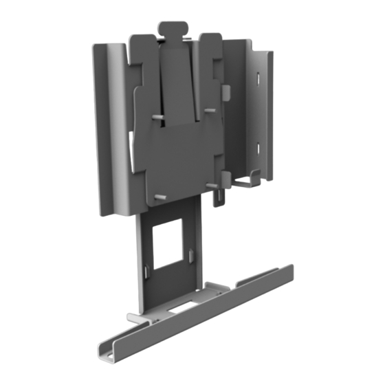
Page 4: Wall Mount Assembly
Wall Mount Assembly Introduction This kit provides a wall mount assembly for the NCR P1532 POS. Kit Contents... -
Page 5: Installation Procedure
Wall Mount Assembly Installation Procedure 1. Mount the Wall Mount Bracket to the wall. Secure the bracket with one of the following: • If there are no studs, mount the bracket with two hollow wall anchors (1/4" diameter x 2 1/4" length). •... - Page 6 Wall Mount Assembly 2. Insert the power brick into the power supply bracket (AC connector on top). Route the cables into the pass–through slot. Fasten the cables together using the Cable Management Straps. 3. Push the Tamper Proof Cover to the bottom of the wall mount bracket.
- Page 7 Wall Mount Assembly 4. Tighten the thumbscrews (2) to secure the tamper proof cover. 5. Mount the Wall Mount Plate to the back of the terminal head. 6. Secure the plate with M4 x16 screws (4).
- Page 8 Wall Mount Assembly 7. Install the terminal head to the wall. a. Hook the wall mount plate to the wall mount bracket on the wall. b. To ensure that the latch is engaged, press on the spring clip in the direction indicated below.
- Page 9 Wall Mount Assembly c. To remove the terminal head from the wall mount, press on the spring clip and pull the terminal head upwards. Note: Additional hardware is provided for a wall mount with a third–party VESA mounting arm.
Need help?
Do you have a question about the 7754-K312 and is the answer not in the manual?
Questions and answers