
Related Manuals for Meusburger profiTEMP IM


Summary of Contents for Meusburger profiTEMP IM
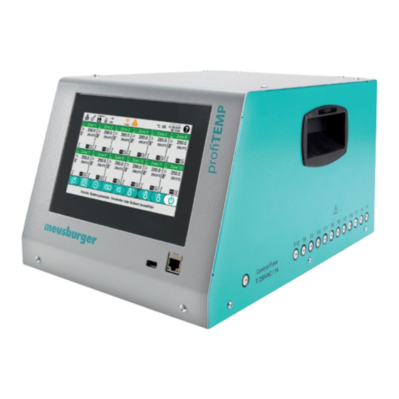
- Page 1 Hot runner controller profiTEMP IM Manual Download the manual in additional languages at www.profiTEMP.de...
-
Page 3: Table Of Contents
CONTENTS Introduction First read, then start Safety Instructions Design and connections Front/side view Rear view Mains connection Digital input / alarm output XM1 Mould connection Operation Switch on / Switch off Screen layout Operating instructions 4.3.1 Buttons and input fields 4.3.2 Edit values 4.3.3... - Page 4 5.3.2 Monitor heating currents 5.3.3 Detecting leaks Control behaviour Alarms and error handling Service Fuse replacement Firmware update Appendix Technical specifications Overview of zone parameters Overview of system parameters Declaration of conformity Version history documentation...
-
Page 5: Introduction
The profiTEMP IM is available in three versions. These differ only in the design of the plug assignment of the mould con- nection (ä 3.5 Mould connection). - Page 6 Electrical waste and electronic devices and components are subject to hazardous waste treatment and may only be disposed of by authorised specialist companies. Meusburger as manufacturer in the sense of the Electrical and Electronic Equipment Act (ElektroG), which transposes the European WEEE Directive 2002/96/EC into German law, is registered under the WEEE registration number DE 66448978.
- Page 7 Chapter 1 — Introduction Warning / caution This safety-relevant symbol warns of a possible malfunction or danger. Failure to comply may result in personal injury or serious damage to property. Information / notes This symbol indicates additional information for better understanding. Instruction / example This symbol indicates detailed explanation of operating steps for a function.
-
Page 8: Safety Instructions
Manual profiTEMP IM SAFETY INSTRUCTIONS All instructions must be read and followed in full. All persons responsible for the positioning, commissioning, operation, maintenance and servicing of the device must be suitably qualified and must: » pay close attention to this manual, »... - Page 9 In all cases where the adjacent symbol is visible on the device, it is essential to observe the safety instructions marked with this symbol/sign/sticker for the profiTEMP IM. In all cases, this manual must be consulted. Do not leave the packaging material lying around carelessly, plastic film/styrofoam parts may pose a danger to others.
-
Page 10: Design And Connections
Manual profiTEMP IM DESIGN AND CONNECTIONS FRONT/SIDE VIEW USB port Network connection Operating screen (7" touch screen) Heating fuses Control fuse REAR VIEW Main switch Mould connection XA1 and XA2 Fan / air outlet Digital input / alarm output XM1... -
Page 11: Mould Connection
Chapter 3 — Design and connections MOULD CONNECTION The profiTEMP IM has two mould connections (XA1 and XA2). The pin assignments for heaters and thermocouples de- pend on the three device variants. Variant 1 — MEU/001 | RH 1200/12/001/WI24B/32A Variant 2 — 121 | RH 1200/12/121/WI24B/32A... -
Page 12: Operation
Manual profiTEMP IM OPERATION SWITCH ON / SWITCH OFF After making all the necessary connections to the device, set the main switch on the back of the device to position 1 / ON to put the device into operation. The device can be de-energised in the same way (position 0 / OFF). -
Page 13: Edit Values
Select zones and enter parameters Enter system parameters After switching on the profiTEMP IM you start on the ä 4.4.1 Home page with process data and status information. You can switch between ä 4.4.1 Home page and ä 4.4.2 Status page (A). -
Page 14: Select And Deselect Zones
Manual profiTEMP IM The selected zones are reduced or increased by the same value. In this case the sign key is enabled. Positive numbers increase the values of all selected zones, negative num- bers decrease them. SELECTION FROM A LIST OF VALUES For parameters with a defined value list (here: digital input function), the selection is made directly in the list. -
Page 15: Screen Pages
10 mA 08:10:24 Switch-on Boost profiTEMP IM offers to start the ä [P008] Boost for a period of 5 minutes. After 5 mi- According to the settings, the boost must be deactivated again manually. nutes, the temperature increase is reversed without user intervention and regulated Start Boost once with 5 minutes back to the set point. -
Page 16: Home Page With Detail Zone Field
Manual profiTEMP IM 4.4.1.1 HOME PAGE WITH DETAIL ZONE FIELD Program 1 pT IM 072122O Tapping on a zone field opens the detail zone field of the zone. No °C 01.08.2022 10 mA 08:10:24 entries can be made in the detail zone field itself. -
Page 17: Zone Field In Other Operating Modes
Chapter 4 — Operation the status of the PID control parameters. The symbol is hidden if the automatic calculation of the control parameters ä [P030] Identification is switched off. In this case, the stored control parameters are used for control. The symbol is visible when an automatic calculation of the control parameters [ä... -
Page 18: Colour Code In The Header Of The Zone Field
Manual profiTEMP IM Zone 1 The heating is switched off, no temperature is displayed. The zone is not monitored. 4.4.1.5 COLOUR CODE IN THE HEADER OF THE ZONE FIELD The colour field (D) in the zone field provides information about the status of the zone. -
Page 19: Set Point Value Input
Chapter 4 — Operation 4.4.3 SET POINT VALUE INPUT The screen page for entering the set point value is called up. The zone field A in a zone contains the following information: Program 1 pT IM 072122O °C 01.08.2022 » 08:10:24 the zone number [°C]... -
Page 20: Header
The key symbol indicates the authorisation level for changing the setting parameters. The user has access to the parameters that don’t require a login. This authorisation level applies, for example, after switching on the profiTEMP IM. The user has logged in with the valid password and has access to all parameters. - Page 21 Chapter 4 — Operation RESET PASSWORD If you lose your own password, it can be reset to the factory password user . To do this, tap the button. When prompted to enter the old password, enter defaultpw. Confirm the prompt to reset the password.
-
Page 22: Footer
Manual profiTEMP IM CHANGE LANGUAGE The two-digit country code indicates the selected language of the user interface (DE = German, EN = English, PL = Polish, etc.). Program 1 pT IM 072122O Tapping the country code in the header displays the language selec- °C... -
Page 23: Save Mould Programs In The Program Memory Of The Controller
31.07.22/07:20:00 Program 3 Programs The button can be used to reset the profiTEMP IM to the factory settings. This requires a ä Login (ä 4.7 Reset- ting the device to factory settings). 4.5.1 SAVE MOULD PROGRAMS IN THE PROGRAM MEMORY OF THE CONTROLLER Select the memory location in the left-hand window. -
Page 24: Load Mould Program From The Program Memory Of The Controller
Manual profiTEMP IM The name of the mould program appears in the left window on Programm 1 pT IM 072122O °C 01.08.2022 08:10:24 the selected memory location. Program memory No USB available 10.10.22/07:00:00 The name of the mould program just saved is displayed in the Program 1 header. -
Page 25: Handling Of Mould Programs With Usb Stick
Mould programs can be saved on a USB stick. Mould programs stored there can be used for a safe restore or transferred to another profiTEMP IM. The handling of mould programs with a USB stick is only enabled when a USB stick is inserted into the device. -
Page 26: Process Monitoring
Manual profiTEMP IM PROCESS MONITORING The process monitoring function is primarily intended to detect plastic leaks in the hot runner mould. Leakage monitor- ing only makes sense if a temperature sensor is present in the vicinity of an expected leakage in order to quickly detect a change in the process. -
Page 27: Resetting The Device To Factory Settings
Chapter 4 — Operation RESETTING THE DEVICE TO FACTORY SETTINGS The controller can be reset to two different states. Only zone parameters Only the zone-specific setting values are reset. For example, if all zone-specific settings for a new mould are to be made starting from the factory settings, but the remaining settings are to remain unaffected. All data All settings are reset to the factory settings. -
Page 28: Setting Parameters And Mode Of Operation
Manual profiTEMP IM SETTING PARAMETERS AND MODE OF OPERATION Changing some parameters is only possible after a ä Login. These parameters are marked with a In this chapter the default value of a parameter at the setting range is marked with square brackets []. -
Page 29: Residual Current Limit
Chapter 5 — Setting parameters and mode of operation Smallest possible definable set point value 5.1.5 RESIDUAL CURRENT LIMIT [SP05] MAXIMUM RESIDUAL CURRENT Setting range 0 (deactivated) — [60] mA The residual current monitoring detects leakage currents that occur due to moisture in the mould or insulation damage. If the measured residual current is higher than the residual current limit, the heaters of the zones where the output level was greater than 0% when the error occurred are de-energised. -
Page 30: Action In The Event Of Sensor Break
Manual profiTEMP IM Mains phase missing Current too high Heater output too high or short circuit detected Channel data error Checksum error in channel data System data error Checksum error in system data Identification error Error in determining the control parameters Sensor short circuit TCs A short circuit was detected in a thermocouple. -
Page 31: Set Up Zones
Chapter 5 — Setting parameters and mode of operation SET UP ZONES To set up, all mould-specific settings must be made. 5.2.1 HEATING UP [SP39] HEATING MODE All zones of the controller are heated in the same way. The setting is therefore made in the system parameters. Setting range [Direct], automatic ramp, relay heating, start-up mode DIRECT... -
Page 32: Handling For Heating Up
Manual profiTEMP IM If desired, a zone can automatically switch to manual mode when a sensor error is detected. This is defined in system parameter ä [SP38] Automatic sensor break . Of course, a zone can also be operated in manual mode without a sensor error. -
Page 33: Standby & Boost
Chapter 5 — Setting parameters and mode of operation switched off. 5.2.3 STANDBY & BOOST [P007] STANDBY Setting range 0 — [100] — 999.0 °C | 0 — 1830.2 °F The use of the standby function is recommended to protect the moulds and to reduce energy costs during downtimes. The set point value is reduced by the set value at the push of a button. -
Page 34: Monitoring
Manual profiTEMP IM MONITORING To monitor the hot runner control, the corresponding limit values must be set for temperatures and heating currents, among other things. 5.3.1 MONITOR TEMPERATURES [SP32] UPPER TEMPERATURE ALARM Setting range 0 — [5] — 99 °C | 0 — 178.2 °F For temperature monitoring, a tolerance range can be set above the set point value. -
Page 35: Control Behaviour
Chapter 6 — Setting parameters and mode of operation CONTROL BEHAVIOUR The PID control parameters ä [P034] Proportional band, ä [P035] Hold-off time and ä [P036] Reset time determine the behaviour of the controller and can be determined automatically by the ä [P030] Identification when heating up the zones. -
Page 36: Alarms And Error Handling
Manual profiTEMP IM ALARMS AND ERROR HANDLING All errors and alarms pending in the zones can be seen on the ä 4.4.1 Home page and ä 4.4.2 Status page. ALARM SYMBOL IN THE HEADER The alarm symbol in the header indicates that there is an alarm in at least one zone. Exceptions to this are tem- perature limit alarms;... - Page 37 Chapter 6 — Alarms and error handling Symbol Meaning Response Cause » Sensor polarity reversal Heating is switched off (output Wiring = 0%) Thermocouple connected with wrong polarity » Sensor short circuit Heating is switched off (heating Sensor connection relay opens heating circuit). Er- The temperature displayed does not cor- ror must be acknowledged respond to the temperature at the measur-...
- Page 38 Manual profiTEMP IM Symbol Meaning Response Cause » Process monitoring Spillage » Ageing of the heating The output value exceeds the tolerance system window of the process monitoring. » Setting limit too low In addition, the following information on temperature alarms is listed in the detail zone field.
-
Page 39: Service
Step 3 Perform update » Switch off profiTEMP IM, insert the prepared USB stick into the USB port of the device and switch on the device. » A dialogue box appears on the start screen where you select the Firmware Update button. -
Page 40: Appendix
The heating outputs of zones 1, 4, 7, 10 and 2, 5, 8, 11 and 3, 6, 9, 12 are each assigned to a phase L1/L2/L3. MOULD CONNECTION Mains plug: Wieland WI 70.300.2440.0 Pin assignment: Meusburger Standard (001) HEATING CURRENT MEASUREMENT Measuring range 0 to 16 A per power output Resolution 0.1 A (accuracy +/- 0.1 A) -
Page 41: Overview Of Zone Parameters
Chapter 8 — Appendix Installation altitude above sea level max. 2000 m AMBIENT TEMPERATURE Operation 0 — 45 °C, transport and storage -20 — 70 °C CLIMATE APPLICATION CLASS Relative humidity < 75% annual average, no condensation MECHANICS Dimensions: 215 x 260 x 400 (H x W x D in mm) Weight: 9.8 kg OVERVIEW OF ZONE PARAMETERS The parameters marked with... -
Page 42: Declaration Of Conformity
J (FeCu-Ni) SP13 Switch-on delay 0 (disabled) DECLARATION OF CONFORMITY All products have been developed and manufactured in compliance with applicable European standards and directives. The declaration of conformity can be requested from Meusburger. VERSION HISTORY DOCUMENTATION Date Version Modification 22.03.2023 1.00.02... - Page 44 Rev. 1.00.02 Subject to technical changes Meusburger Georg GmbH & Co KG | Kesselstr. 42 | 6960 Wolfurt | Austria | P +43 5574 6706 office@meusburger.com | www.meusburger.com...
Need help?
Do you have a question about the profiTEMP IM and is the answer not in the manual?
Questions and answers