Table of Contents
Advertisement
Quick Links
Advertisement
Table of Contents

Related Manuals for Meusburger profiTEMP+


Summary of Contents for Meusburger profiTEMP+
- Page 1 Integrated hot runner controller profiTEMP+ SYSTEM Start-up and service manual...
-
Page 3: Table Of Contents
INHALT Preface Versions Documentation Information about this manual 1.2.1 Disclaimer 1.2.2 Terms of delivery 1.2.3 Warranty conditions Security 1.3.1 Target group of these instructions 1.3.2 Intended use 1.3.3 Danger and warning notices 1.3.3.1 Other notes 1.3.4 Safety instructions 1.3.5 Transportation and storage 1.3.5.1 Transport 1.3.5.2... - Page 4 4.2.2.1 Slide-in card pT+HTC 06/15 4.2.2.2 Cover plates 4.2.3 pT+CUR 4.2.4 pT+IO 4.2.5 pT+ ERJ 4.2.6 Residual current transformer RCT Electrical installation 4.3.1 Preparation pT+Rack for wiring 4.3.2 Power loss 4.3.3 Power supply electronics 4.3.3.1 pT+CUR & pT+IO 4.3.4 Mains voltage for heating outputs 4.3.5 Protective Ground Sensor / heating connection...
-
Page 6: Preface
(VDE regulations, Equipment Safety Act, accident prevention regulations of the employers' liability insurance associations, etc.). Meusburger Georg GmbH & Co KG reserves the right to make changes to this manual or the product described in it without prior notice if these serve to improve the product and/or technical progress. -
Page 7: Target Group Of These Instructions
The system is operated via a PC with Meusburger Georg GmbH & Co KG's own PC software installed (flexotempMANAGER project planning and configuration tool or TEMPSoft2 operating software) or via a bus connection to the machine control system. -
Page 8: Transportation And Storage
1.3.7 DISPOSAL Meusburger Georg GmbH & Co KG as a manufacturer within the meaning of the ElektroG (Electrical and Electronic Equipment Act), which transposes the European WEEE Directive 2002/96/EC into German law, is registered under the number WEEE registration number DE 66448978. The components of the profiTEMP+ SYSTEM are also taken into account. -
Page 9: Product Description
Kapitel 1 — Product description PRODUCT DESCRIPTION GENERAL DESCRIPTION profiTEMP+ SYSTEM is suitable for heating hot runner tools in injection molding machines. For this purpose, the integrable hot runner controller is connected directly to the hot runner in the injection mold via connecting cables. profiTEMP+ SYSTEM supplies an electric current to the hot runner heaters in the injection mold during operation. -
Page 10: Labeling
Serial number The number combination of the serial number consists of the production date and a consecutive number. The number combination allows Meusburger Georg GmbH & Co KG to clearly identify the device version, soft- ware and hardware version and is used for traceability purposes. -
Page 11: Structure And Connections
Kapitel 2 — Structure and connections STRUCTURE AND CONNECTIONS DANGER In all cases where the adjacent symbol appears on the device, it is essential to observe the safety instructions for the profiTEMP+ SYSTEM marked with this symbol/sign/sticker. This commissioning and service manual must be consulted in all cases. -
Page 12: Fieldbus (Optional)
LED LNK green shows the connection to the physical network. LED RCV yellow indicates network activity. 3.1.4 CANOPEN/RS485 Depending on the device version, either CANopen or an RS485 interface is available. Plug Function CAN (Pin) Function RS485 (Socket) CAN-L CAN-H www.meusburger.com... -
Page 13: Technical Data
Kapitel 3 — Structure and connections 3.1.5 TECHNICAL DATA Power supply USB, front Supply voltage: 24VDC ±10% (PELV), external fuse max. 3.15A F required Electrical safety / EMC (e.g. Siba 189000.3,15 / fuse must blow safely at 7.5A in 120 s) IEC 61010-1:2010/AMD1:2016/AC:2019 Power consumption: max. -
Page 14: Measuring Inputs For Leakage Current Transformers
Connection cable < 30 m switch cabinet surfaces must not be less than 20 mm. Interfaces/communication CAN to pT+RACK Transmission speed 500 kBit Max. permissible bus length 100 m Connection: Terminal Electrical safety / EMC IEC 61010-1:2010/AMD1:2016/AC:2019 EN 61010-1:2010/A1:2019+ A1:2019/AC:2019 www.meusburger.com... -
Page 15: Pt+Rack
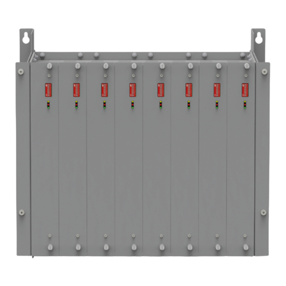
Kapitel 3 — Structure and connections pT+RACK The pT+RACK is the frame for holding the pT+HTC 06/15 plug-in cards. Racks are available to accommodate 2, 4, 6 and 8 plug-in cards. Heaters and thermal sensors are not connected directly to the plug-in cards but to the connections on the backplane of the pT+RACK. -
Page 16: Thermocouple Inputs
Power supply electronics (Uel): Cable length < 30 m pT+HTC 06/15 The pT+HTC 06/15 plug-in card has no connections. 3.4.1 TECHNICAL DATA Power supply for heating Power supply electronics 230 VAC, 50 Hz/60 Hz, +29 %, -14 % 24 VDC ±10 % (PELV), external fuse protection www.meusburger.com... -
Page 17: Measuring Inputs External Cold Junction
Kapitel 3 — Structure and connections Power consumption 2 W 100% duty cycle permanently at ambient temperature <= 25 °C At ambient temperatures above 25 °C, the simultaneity factor can be Sensor inputs reduced to up to 85 % depending on the average output levels and their Thermocouple type: Fe CuNi type J (-35-500 °C), Fe CuNi type L (-30-500 duration. - Page 18 Dimensions (HxWxD in mm): 99 x 22.5 x 114.5 Weight: 0.3 kg To ensure sufficient ventilation, the minimum distance of 50 mm upwards and 50 mm downwards to neighboring devices and control cabinet surfaces must not be exceeded. www.meusburger.com...
-
Page 19: Installation And Start-Up
Kapitel 4 — Installation and start-up INSTALLATION AND START-UP The basic system structure is generally explained in the commissioning and service manual using a pT+RACK with 4 slots. The de- sign with regard to the number of zones may vary. The following work must be carried out before commissioning the system. -
Page 20: Mechanical Installation
The ventilation or air conditioning of the control cabinet must be set up in such a way that the ambient conditions of the compo- nents are maintained during continuous operation. NOTE The type plate is located on the top right-hand side of the pT+RACK. www.meusburger.com... -
Page 21: Slide-In Cards Pt+Htc 06/15 / Fitting Cover Plates
Kapitel 4 — Installation and start-up 4.2.2 SLIDE-IN CARDS PT+HTC 06/15 / FITTING COVER PLATES 4.2.2.1 SLIDE-IN CARD pT+HTC 06/15 Step 1 Insert the pT+HTC 06/15 plug-in cards into the pT rack in the guide brackets at the top/bottom. Ensure that the plug connectors engage. Step 2 Lock the pT+HTC 06/15 plug-in card at the top and bottom. -
Page 22: Electrical Installation
When designing and planning the control cabinet or the appliance connection box, the power loss of the installed components of the profiTEMP+ SYSTEM system must always be taken into account. This is mainly calculated from the plug-in cards pT+06/15 as follows: www.meusburger.com... -
Page 23: Power Supply Electronics
Kapitel 4 — Installation and start-up (x)) = (I x 0,07 Ω + I x 1,2 V VerlustAusgang Ausgang Ausgang = P( (1)) + ... + P( (n)) + 2 W Verlust VerlustAusgang VerlustAusgang 4.3.3 POWER SUPPLY ELECTRONICS ASSEMBLY/INSTALLATION MATERIAL Install the supply voltage according to the specifications in chapter 3.3.5 Technical data. -
Page 24: Protective Ground
The cable cross-sections of all connecting cables must be designed in accordance with the national standards applicable in the respective country for the corresponding installation type and location. The maximum ambient temperature must be taken into account when selecting the cables. www.meusburger.com... -
Page 25: Sensor / Heating Connection
Kapitel 4 — Installation and start-up The protective earth connection must be located close to the mains voltage con- nection. Connect the protective earthing to the pT+RACK and to the moving part at the bolt marked with the earthing symbol. Earth the pT rack frame and moving part via bolts. -
Page 26: Heating Connection Cable
The maximum ambient temperature must be taken into account when selecting the cables. » Cable with blade receptacle 6.3/0.8; fully insulated for connection to Faston blade terminals DANGER The connection cables for the heaters may only be connected when the profiTEMP+ SYSTEM is de-energized. www.meusburger.com... -
Page 27: Can-Bus (Intern)
Kapitel 4 — Installation and start-up MONTAGE Connect the heating connection cables to Faston blade terminals O1-O6, O1N- O6N and/or O7-O12, O7N-O12N for each backplane. The zones are numbered consecutively according to the setting of the DIP switch (1...32dec) on the controller card pT+HTC 06/15 (chapter ä 7.1 Addressing the components with CAN interface). -
Page 28: Terminating Resistor
The other bus termination on the CAN bus is located on the other end device of the line topology of the CAN bus. » If one of the pT+HTC 06/15 plug-in cards is the terminal device, the termi- nation is carried out via the DIP switch of the corresponding pT+HTC 06/15 plug-in card located on the inside of the backplane. www.meusburger.com... -
Page 29: Setup And Service
Kapitel 5 — Setup and service SETUP AND SERVICE DANGER In all cases where the adjacent symbol appears on the appliance, it is essential that you observe the safety instructions for the profiTEMP+ SYSTEM marked with this symbol/sign/sticker. This commissioning and service manual must be consulted in all cases. When installing and replacing individual components during servicing, ä... -
Page 30: Replacing Individual Components And Setup
After switching the power supply back on and waiting for the start-up time of all components, neither the the LED displays (see chapter ä 6 Troubleshooting) » the flexotempMANAGER project planning and configuration tool » the visualization of the machine control system to check that the profiTEMP+ SYSTEM is running properly again after replacing the component. www.meusburger.com... -
Page 31: Change The Fuse To Pt+Htc 06/15
NAGER project planning and configuration tool or USB. Proceed as follows. 5.3.1 UPDATE VIA flexoTEMPMANAGER Step 1 Load the current firmware from the Meusburger website www.meusburger.com or via the auto-update function of the flexo- TEMPMANAGER. Step 2 Read out the project from pT+CUR. -
Page 32: Troubleshooting And Elimination
LED off: e.g. not supplied with voltage, other defect Check wiring Check whether CAN controller is defective 6.2.3 INCORRECT SLAVE TYPE IN PROJECT PLANNING The pT+CUR detects that a component other than the one included in the project planning is registered in the slot. www.meusburger.com... -
Page 33: Phase/Fuse Faults
Kapitel 6 — Troubleshooting and elimination Reason Inspection/elimination False Slavetype Check project planning Check address settings Perform setup 6.2.4 PHASE/FUSE FAULTS The hot runner controller monitors the status of the fuses in the heating circuits. A phase failure is also detected and signaled. Reason Inspection/elimination Fuse defective... -
Page 34: 6.2.11 Sensor Polarity Reversal
25°C to 45°C, the simultaneity factor can be reduced to up to 70% depending on the average output levels and their duration. Plug connection to fan faulty Check plug connection/connecting cable, replace if necessary Mechanischer Defekt am Lüfter Check fan www.meusburger.com... -
Page 35: Appendix
Kapitel 7 — Appendix APPENDIX ADDRESSING THE COMPONENTS WITH CAN INTERFACE The CAN bus is used to transmit information between the components of the system. Each CAN component has a node ID, which is set via DIPs or rotary switches, depending on the component. Only the addressing possible on the component according to the coding switch is entered in the table. -
Page 36: Accessories
Item number Designation Bemerkung CANopen Stecker DECLARATION OF CONFORMITY All products have been developed and manufactured in compliance with applicable European standards and directives. The decla- ration of conformity can be requested from Meusburger Georg GmbH & Co KG. www.meusburger.com... - Page 38 Rev. 0.00.04 Subject to technical changes Meusburger Georg GmbH & Co KG | Kesselstr. 42 | 6960 Wolfurt | Austria | T +43 5574 6706 office@meusburger.com | www.meusburger.com...
Need help?
Do you have a question about the profiTEMP+ and is the answer not in the manual?
Questions and answers